Table of Contents
Advertisement
Advertisement
Table of Contents

Related Manuals for Hanna Instruments GROLINE HI981420


Summary of Contents for Hanna Instruments GROLINE HI981420
- Page 1 HI981420 HI981421 GROLINE MONITOR...
- Page 2 If you need additional technical information, do not hesitate to e‑mail us at tech@hannainst.com or view our worldwide contact list at www.hannainst.com. All rights are reserved. Reproduction in whole or in part is prohibited without the written consent of the copyright owner, Hanna Instruments Inc., Woonsocket, Rhode Island, 02895, USA.
-
Page 3: Table Of Contents
1. PRELIMINARY EXAMINATION ..................2. SAFETY MEASURES ......................3. SPECIFICATIONS ......................4. DESCRIPTION ......................... 4.1. SIGNIFICANCE OF USE ..................... 4.2. GENERAL DESCRIPTION .................... 4.3. PRODUCT DIAGRAM ....................4.4. KEYPAD DESCRIPTION ....................5. GENERAL OPERATIONS ....................5.1. -
Page 4: Preliminary Examination
Remove the protective film from the Monitor. Notify your nearest Hanna Instruments Customer Service Center if damage is observed. Each... -
Page 5: Specifications
3. SPECIFICATIONS pH specifications Range 0.00 to 14.00 pH, 0.0 to 14.0 pH* Resolution 0.01 pH, 0.1 pH Accuracy (@25 ºC/77 ºF) ±0.05 pH, ±0.1 pH one or two‑point calibration (using pH 4.01, 7.01, 10.01 Calibration buffers) using auto buffer recognition one‑point calibration using quick calibration solution Temperature compensation automatic: 0.0 to 60.0 °C;... - Page 6 Temperature specifications Range 0.0 to 60.0 °C / 32.0 to 140.0 °F Resolution 0.1 °C / 0.1 °F Accuracy ±0.5 °C /±1.0 °F Additional specifications Measurements (pH, EC, TDS, temperature) Min/Max/average/status logged continuously at 15 minutes interval Recall graphic modes Automatic logging Export on USB‑C flash drive or PC Log files in CSV format...
- Page 7 Probe specifications Probe HI1285‑8 HI1285‑9 Preamplified inline Description Preamplified pH/EC/Temp probe pH/EC/Temp probe Reference Single junction Ag/AgCl Triple internal junction Ag/AgCl Junction Cloth PTFE Electrolyte Polymer Max. pressure (25 °C) 0.2 bar 8.0 bar pH range 0.00 to13.00 pH 0.00 to 12.00 pH pH tip shape Spherical (dia: 6.0 mm) Spherical (dia: 5.5 mm)
-
Page 8: Description
4. DESCRIPTION 4.1. SIGNIFICANCE OF USE pH in agriculture pH affects the ability of plant roots to absorb nutrients. Calcium, phosphorus, potassium and magnesium are likely to be unavailable to plants in acidic soils. Plants have difficulty absorbing copper, zinc, boron, manganese and iron in basic soils. By managing pH, you can create an ideal environment for plants and often discourage plant pests at the same time. - Page 9 EC in agriculture EC stands for electrolytic conductivity, or the ability of a solution to conduct an electric current. Current travels efficiently through water with high levels of salt present (high EC), and less so through pure water (low EC). EC indicates how much dissolved salt is in a given sample. That's why EC is also referred to as TDS (total dissolved solids).
-
Page 10: General Description
4.2. GENERAL DESCRIPTION GroLine Monitor is designed to offer you the combination of pH, conductivity (or total dissolved solids) with temperature measurements. All operations and settings, including calibration buffers and temperature scale selection, are included in a easy to use Monitor setup. -
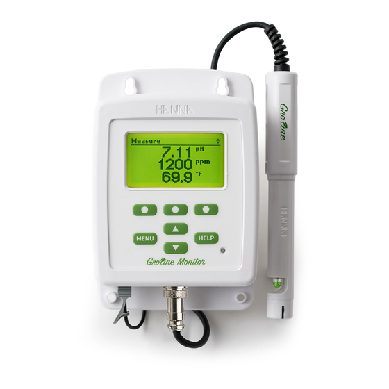
Page 11: Product Diagram
4.3. PRODUCT DIAGRAM FRONT VIEW BOTTOM VIEW 1. Mounting holes 2. Liquid Crystal Display (LCD) 3. USB C port 4. Power cable 5. DIN probe connector 6. Ambient light sensor 7. Keypad area... -
Page 12: Keypad Description
BACK VIEW 4.4. KEYPAD DESCRIPTION access to Quick calibration, logged history, pH/EC/temperature options and General setup in menu mode scroll the menu items /adjust the settings in measurement mode changes the screen: three parameter screen (pH, EC and temperature), single parameter screen and plot display enter/exit help menu virtual function keys ‑... -
Page 13: General Operations
5. GENERAL OPERATIONS 5.1. STARTING UP THE MONITOR Detailed below is a general outline of the steps required to perform accurate measurements. 1. Mount the Monitor on a stable support wall. 2. Connect the HI1285‑8 HI1285‑9 probe to the Monitor. 3. -
Page 14: Connecting The Probe
GroLine Monitor and probe can be used for fertilizer tank monitoring. The system continuously measures the EC and pH of the tank. The probe (HI1285‑8 or HI1285‑9) should be placed in a location representing the bulk properties of the tank. 5.2. - Page 15 HI1285‑9 With the monitor turned off, connect the HI1285‑9 probe to the DIN socket on the bottom of the monitor by aligning the pins and pushing in the plug. Tighten the nut to ensure a good connection. Remove the protective cap from the probe before taking any measurements. Please note that the probe needs to be calibrated before installing in a pipe line or tank.
-
Page 16: Inline Mounting Recommendations
5.3. INLINE MOUNTING RECOMMENDATIONS Verify the maximum pressure of your circuit before mounting the probe. Ensure that the pressure does not exceed 8 bars. Prepare the circuit with 3/4 NPT threaded T‑junction so that the probe can be mounted. Recommended pipe size is 2”. Perform a test measurement before inline mounting the probe to verify its functionality. -
Page 17: Tank Mounting Recommendations
5.4. TANK MOUNTING RECOMMENDATIONS The electrode can be mounted inside the water tank using HI60501 special immersion electrode holder. In order to do this mounting check if your water tank is compatible with this particular immersion electrode holder. For assembly please follow steps detailed below: •... -
Page 19: Electrode Conditioning And Maintenance
5.5. ELECTRODE CONDITIONING AND MAINTENANCE Tiny air bubbles may form inside the pH sensor bulb during transport. The electrode cannot function properly under these conditions. Remove the bubbles by “shaking down” the electrode as you would do with a glass thermometer. If the pH bulb and/or junction are dry, soak the probe in HI70300 Storage solution for at least one hour. - Page 20 EC Cell cleaning and inspection 1. As preventative maintenance measure, rinse the probe with tap water on a weekly basis. Monthly, a more thorough cleaning is advised. Clean the EC sensor (slot in bottom of probe) with a non‑abrasive detergent, or, alternatively, refer to cleaning step 4 below. 2.
-
Page 21: Monitor Menu
5.6. MONITOR MENU 5.6.1. MENU OPTIONS Press MENU key to display a list of configurable options. Highlight the desired option using ▲▼. Quick Calibration Press Start to enter the Quick Calibration screen. pH and Conductivity are displayed and the quick calibration procedure is initiated (see Operational guide). - Page 22 3. Press GLP to display the last pH calibration data and up to four previous ones. Use ▲▼ to display previous Calibration data. The newest data is in position 1. Three options are available after pressing EC: CAL, Setup and GLP.
-
Page 23: General Setup
5.6.2. GENERAL SETUP Backlight Default state is Auto (in low‑light conditions backlight level is automatically adjusted to dim). This function, together with the integrated ambient sensor on the keypad, works to automatically adjust the backlight of the LCD. Press Auto and then Modify to adjust the minimum backlight intensity level. - Page 24 Date / Time Press the Modify key to change the date/time. Press the functional ► key to highlight the value to be modified (year, month, day, hour, minute or second). Use the ▲▼ keys to change the value. Press the Accept key to confirm changes or Escape to return to general menu without saving the new date or time.
- Page 25 Decimal Separator Option: Comma ( , ) or Period ( . ) Press the functional key to select the desired decimal separator or press Escape to return to general menu without saving the new format. The decimal separator is used on the measurement screen and CSV files.
-
Page 26: Ph Setup
Meter Information Press the Select key to view the model, serial number, firmware version and selected language. Press Escape to return to the general menu. Reset Monitor defaults Press the Select key to activate Reset Monitor defaults settings. Press Accept to initiate procedure or Cancel to return to the general menu without reset. - Page 27 Set the Alarm Low and Alarm High as boundaries of acceptable pH variation. If these boundaries are exceeded, the display flashes as a visual indication that the pH of the desired solution has changed. Use ▲ ▼keys to set pH alarm value. Press the Accept key to confirm the value or Escape to return to the general menu without saving the new value.
-
Page 28: Ec Setup
5.6.4. EC SETUP Note: Prior to setting EC alarm limits, select desired Mode of operation, TDS or EC. Alarm High and Alarm Low in the EC menu have two options, Enable or Disable. When alarms are set to Enable press Modify to adjust EC alarm value. Use ▲... -
Page 29: Temperature Setup
Calibration Timeout Calibration Timeout feature is used to set a scheduled reminder for calibration or service. It can be configured 1‑30 days or disabled (no message). A reminder message will be displayed with the measurement indicating it's time to service the probe. Mode Press functional key to change EC with TDS mode. - Page 30 Press the Accept key to confirm the value or Escape to return to the general menu without saving the new value. When selected temperature unit is °F, alarm values will be displayed in same unit. Temperature Unit Option: °C or °F Press the functional key to select the desired temperature unit, Celsius or Fahrenheit.
-
Page 31: Alarms
5.6.6. ALARMS The alarm feature provides visual indication that a parameter has diverged from the preferred mea‑ surement readings. Active alarms: when an alarm is activated, the display will flash providing a visual indication from a distance that an alarm set‑point has been triggered. The flashing will stop after the measurement has returned to the configured limits. -
Page 32: Operational Guide
6. OPERATIONAL GUIDE 6.1. PROBE CALIBRATION The probe should be calibrated: • before being installed in the system. • after probe replacement. • daily, if greater accuracy is required. • every 2 weeks as part of routine maintenance (HI1285‑8 only). Every time you calibrate the Monitor use fresh buffer standards and perform electrode maintenance... -
Page 33: Ph Calibration
After saving the calibration the Monitor returns to MENU. Pressing Escape can exit the quick calibration without saving data. If the standard is not recognized or the offset is out of accepted range, "Wrong Standard" is displayed. Refresh the calibration solution, clean and rinse the probe or press Escape to exit cal‑... - Page 34 Two-point calibration From the MENU screen with pH highlighted, press the CAL key to begin the calibration process. The monitor will suggest using the HI70007 pH 7.01 buffer, but it will automatically recognize HI70004 pH 4.01 and HI70010 pH 10.01 buffers. Note: For two-point calibration, the buffer 7.01 pH must be used for the first point.
-
Page 35: Ec Calibration
When the reading is stable and close to the selected buffer, the Confirm key will become available. Press Confirm to accept and store the calibration point 4.01 or 10.01pH. Monitor stores the two‑point calibration information and returns to MENU mode. One-point calibration To perform a one‑point calibration only, press Escape to calibrate in 7.01 pH, or, the Monitor... - Page 36 The calibration can be erased at any time by entering the calibration and pressing Clear. A warning message appears and confirmation for deleting the calibration is requested. Press Accept to confirm or Cancel to exit and return to calibration screen. Note: The GLP history will show "Calibration cleared"...
- Page 37 Calibration messages Wrong Buffer If the buffer is not recognized or the offset is out of the accepted range, “Wrong Buffer“ message is displayed. Change the buffer, clean the electrode and repeat calibration. Wrong Standard If the EC standard is not recognized “Wrong Standard“ message is displayed.
-
Page 38: Glp Information
6.2. GLP INFORMATION Good Laboratory Practice (GLP) refers to a quality control function used to ensure uniformity and consistency of sensor calibrations and measurements. Select pH or EC from MENU and press GLP to review the calibration information. The Monitor can store calibration info from the last five pH and EC calibrations. -
Page 39: Measurement Mode
6.3. MEASUREMENT MODE Turn ON the Monitor by connecting the power adapter to the power cable socket. After initialization has been completed, the controller displays the measurement screen. • Ensure the probe is installed and calibrated. • Install the probe in the tank and ensure that the bottom 4 cm are submersed in the sample solution. - Page 40 The first two functional buttons select the parameter, whereas the title bar indicates currently selected parameter unit. Press Details to access information regarding selected parameters: current reading, Max / Min read‑ ing and average. Status bar messages Whenever an event is triggered, the status bar will display it on measure screen. Possible events: •...
- Page 41 • "Alarm High/Low pH / EC/TDS / Temp." ‑ measurements have exceeded the specified High or Low limits. The backlight and the affected parameter will blink. Note: For same parameters, warnings will not be visible while "Alarm High/Low" message persists. This has higher priority than warnings.
-
Page 42: Data Storage
7. DATA STORAGE GroLine Monitor logging system automatically saves measurement data. Stored data can be accessed two ways: either from the measurement screen or from the History menu. Data from the last 24 hours can be accessed directly from the measurement screen. The screen will display a 24 hours summary that includes: •... - Page 43 When date and time aren't set or the real time clock is malfunctioning, "Logging disabled" appears on measure screen (in the status bar) and the backlight starts to blink. To access, press MENU, highlight History and press View. The Monitor will display a 30 days data plot.
-
Page 44: Data Export
Note: If “!” appears in logged data (*.csv and History/Details screen), an alarm is triggered. The symbol for High/Low alarm is added next to Max/Min column of the affected parameter. Note: If “!!” appears in logged data (*.csv and History/Details screen), the probe is used beyond monitor's specifications and the data is not considered reliable. - Page 45 If the USB flash drive is missing or not detected, the monitor displays a warning message: "No flash drive connected". Exporting to PC Highlight History from MENU and press Options function. Connect an USB cable between the PC and monitor. Highlight Export to PC using ▲▼, then press Select.
-
Page 46: Accessories
8. ACCESSORIES pH/EC/TDS probe with built‑in temperature sensor, DIN connector and 2 m (6.6’) HI1285-8 cable Triple junction inline pH/EC/TDS probe with built‑in temperature sensor, 3/4” NPT HI1285-9 threaded body, DIN connector and 3 m (9.8”) cable HI740036P Plastic beaker set, 100 mL (10 pcs.) HI60501 Immersion electrode holder from PVC HI605011... - Page 47 Returned Goods Authorization (RGA) number from the Technical Service department and then send it with shipping costs prepaid. When shipping any instrument, make sure it is properly packed for complete protection. Hanna Instruments reserves the right to modify the design, construction or appearance of its products without advance notice.
- Page 48 World Headquarters Hanna Instruments Inc. Highland Industrial Park 584 Park East Drive Woonsocket, RI 02895 USA www.hannainst.com MAN981420 Printed in ROMANIA...
Need help?
Do you have a question about the GROLINE HI981420 and is the answer not in the manual?
Questions and answers