Table of Contents
Advertisement
Quick Links
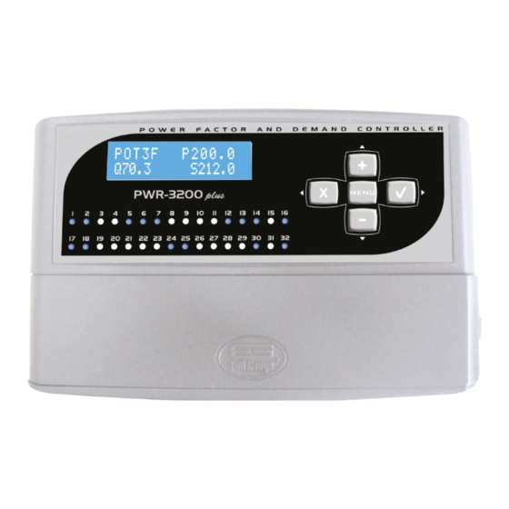
PWR-3200 plus
THREE-PHASE CONTROLLER FOR
DEMAND AND POWER FACTOR
1 - DESCRIPTION
The PWR-3200 plus plus is a controller equipped with 32 outputs, configurable between demand control, power factor control, outputs for
programming "schedule of events" and two alarms. The equipment is able to measure, display to the user and store in an internal data logger
several electrical parameters, such as single-phase voltages and line currents, the currents of each phase, the power, demands and single-phase
and three-phase power factor, the grid frequency, as well as single-phase and three-phase active, reactive and apparent energy.
From the measured demands and power factors, the equipment operates with capacitor banks to correct the power factor, and with the consumer's
energy loads, to control the demand of the electrical system.
2 - APPLICATION
This equipment may be used in any business, which is a consumer of electricity, and wants to manage demand or the power factor, or simply
acquire knowledge about electrical parameters, for monitoring and decision-making.
3 - TECHNICAL SPECIFICATIONS
- Supply: 90 ~ 264 Vac ± 10% (50/60Hz)
- Voltage Range: 50 to 500Vac (50/60Hz)
- Current Range: 5A (expandable with an external CT)
- Command: Alarms: Two relays N.C. (3A Max)
Control Outputs: 30 x N.O. solid state relays (20~250Vac / max 125mA)**
- Dimensions (WxHxD): 220x134x54mm
- Operating temperature: 0 to 40° C
- Operating humidity: 10 to 90% RH (no condensation)
**Solid state relays can only drive AC voltages (VAC) loads
4 - KEYBOARD
Five keys are available for operating the menu.
In general, these keys have the following functions:
If the variable shown is editable, pressing this key will cause it to blink and values can then be increased or decreased. If a variable being
edited (is blinking), pressing this key will validate it with the value chosen. If no editable value is shown, and the menu shows another level
>>>
(represented by the symbol
, or by a numeric index), by pressing this key, you will go to the next menu level. Ex.:
Energies
>>>
Activ En A ( Wh)
If any variable is being edited (blinking) and this key be pressed, the editing will be canceled, and the value of the variable will remain as before
the editing. If there is a previous level and this key is pressed, the menu will go back one level
If a variable is being edited, this key will increase the displayed value (the value that is blinking). If no variable is blinking, this key allows one to
advance in the items on the same menu level. If you are in the "quick view of the electrical parameters" menu, pressing this key for 1 second will
display the menu "record of maximums and minimums." Whilst in the menu "record of maximums and minimums," holding this key for 2 seconds,
will reset the recorded maximum and minimum values.
Note: The increment in the speed of the variable being edited increases with the time the key is pressed.
SIf any variable is being edited, this key decreases the value shown (value that is blinking). If no variable is blinking, this key allows one to
return the items on the same menu level (e.g. Quit menu 2.2 and go to 2.1). If you are in the "quick view of the electrical parameters" menu, pressing
the key for more than 1 second will display the menu "view electrical parameters," where the key
minimums" menu, but goes forward in the menu items.
Note: The increment in the speed of the variable being edited increases with the time the key is pressed.
MENU
If you are in "quick view of the electrical parameters" menu, clicking on the "menu" key will show the "quick access menu." If the menu is in the
"Setting the priority of load shutdown" or "Set the timing for the reconnection of the loads" position, when you press this key for 2 seconds, you can
edit the name of the outputs. After editing, to confirm the allocated name, you must press the key again for 2 seconds.
5 - MENUS
5.1 - Quick View of measured electrical parameters
It is used to display the selected electrical parameters.
To access: go to the main menu, which will be shown when you leave another menu (e.g. from item 3 of the parameters configuration menu, and
pressing the
key).
Note: The values showed on next screens are merely illustrative
02-Power Fact >
or
N Outputs PF Ctr
P01 @ 12
does not go to the "record maximums and
01
Energies
>>>
Activ En A (kWh)
Activ En
Activ En
®
Activ En 3 (kWh)
Rt En A (kVArh)
Rt En B (kVArh)
Rt En C (kVArh)
Rt En 3 (kVArh)
Ap En A (kVAh)
Ap En B (kVAh)
Ap En C (kVAh)
Ap En 3 (kVAh)
VAB VBC VCA
311 309 312
Frequency (Hz)
60.0
PF(3 ) Dem(3 )
0.92(i) 44.411
PF iii A0.91
B0.92
C0.92
Dem(kW) A14.312
B15.265 C14.834
Pow 3
P49.226
Q20.970 S53.507
S(kVA) A17.659
B17.874 C17.974
Q(kVAr) A6.921
B7.005 C7.044
P(kW)
A16.246
B16.444 C16.536
Cur( A) A81.233
B81.546 C81.224
Vol(V) A220.1
B219.2 C221.3
5.2 - Visualize Electrical Parameters
The same as "Quick View of Electrical Parameters" (the screen menus are the same), but differs from the
maximum and minimum menu, but advances in the menu items.
To access: From within the "Quick View of Electrical Quantities" menu, press the
Note: After 2 minutes without touching any key, the menu automatically returns to quick view of the measured electrical parameters.
5.3 - Record of Maximums and Minimums
This menu shows the maximum and minimum values of some parameters.
To access: From within the "Quick View of Electrical Parameters" menu, press the
Note: From within this menu, pressing the
MM1- Max dem reg
Phase A 00.0 kW
MM2- Max Vrms
Phase A 00.0 V
MM3- Min Vrms
Phase A 00.0 V
MM4- Max Irms
Phase A 00.0 A
MM5- Min ind PF
3
1.00
MM6- Min cap PF
3
1.00
Power
2.941
B (kWh)
Single-phase active power
2.925
C (kWh)
2.935
Three-phase active power
8.801
1.216
Single-phase reactive power
1.245
1.198
3.659
Three-phase reactive power
3.138
Single-phase apparent power
3.245
3.148
9.531
Three-phase apparent power
Line voltages
Grid Frequency
Power factor and three-phase demand
Single-phase power factor
Single-phase demand
Active, reactive and apparent three-phase power
Single-phase apparent power
Single-phase reactive power
Single-phase active power
Currents in each phase
Phase voltages
key for 2 seconds.
key for 2 seconds.
key for more than 2 seconds to reset all the recorded values.
Maximum single-phase demand
Maximum voltage of phase
Minimum voltage of phase
Maximum current
Minimum recorded inductive Power Factor (PF)
Minimum recorded capacitive Power Factor (PF)
02
The "iii" or " i" means that the power factor
is inductive. If it would be capacitive, the
letter shown would be "c".
Note:
iii
Phase A B C
key, this does not go to the
Advertisement
Table of Contents

Related Manuals for Full Gauge PWR-3200 plus


Summary of Contents for Full Gauge PWR-3200 plus
- Page 1 1 - DESCRIPTION Rt En A (kVArh) The PWR-3200 plus plus is a controller equipped with 32 outputs, configurable between demand control, power factor control, outputs for 1.216 programming "schedule of events" and two alarms. The equipment is able to measure, display to the user and store in an internal data logger...
-
Page 2: Power Factor (Pf)
"-". But, if instead of this symbol there was a number, it would indicate an error. Likewise, if instead of For finer control, the PWR-3200 plus works by disconnecting and reconnecting loads (when necessary) every 30 seconds. -
Page 3: Data Logger
7.1.3 - Definition of Peak periods and Off-peak periods The PWR-3200 plus has up to six outputs, which can be programmed to turn on and off at certain times of any day of the week. The number of n the parameter it is possible to set the time in which the "off-peak period"... -
Page 4: Setting The Clock And Date
10 - SETTING THE CLOCK AND DATE 12 - FUNCTIONS On the parameters of the menu, you can set the time, date and day of week, respectively. 08-Functions Functions The time setting is done by increasing, or decreasing minutes, which consequently will also set the time. Seconds are not adjusted, but when the time setting is confirmed, they are zeroed. - Page 5 SERIAL - Power is very unbalanced - If the power is unbalanced in a uncommon manner, currents are probably not matched to their respective COMMUNICATION voltages, i.e., current sampling in the CT, at CT1 IN and CT1 OUT, is not the same as the phase 1 voltage, for example. RS-485 Action: Match the voltages, with their respective currents.
- Page 6 COMMON Products: NO NO The electro components of Full Gauge controllers can be recycled or reused if it is disassembled for specialized companies. Disposal: Do not burn or throw in domestic garbage the controllers which have reached the end-of- life.
- Page 7 21 - ANNEXES Configurable Parameters Maximum Standard Unit Parameter Description Minimum Access Code Measured Excess / Time Reference Average Number of PF outputs power Shortage Minimum Power Factor 0.94 15.0 Measured Maximum Power Factor 0.62 0.96 20.9 17.9 46.1 power Reactive power for installed CB 21.2 65535...
- Page 8 Configurable Parameters Description Minimum Maximum Parameter Unit Vol(V) Single-phase voltage Volts Cur( A) Single-phase current 3000 Amperes P(kW) Single-phase active power Kilo Watts 1500 Q(kVAr) Single-phase reactive power 1500 Reactive Kilo Volt Ampere S(kVA) Single-phase apparent power 1500 Kilo Volt Ampere P(3 ) Three-phase active power 4500...
Need help?
Do you have a question about the PWR-3200 plus and is the answer not in the manual?
Questions and answers