
Related Manuals for Rottler SG7MTS


Summary of Contents for Rottler SG7MTS
- Page 1 OPERATION AND MAINTENANCE MANUAL 8029 S 200th St. Kent, WA 98032 USA | www.rottlermfg.com | Ph: 253-872-7050 | Fax: 253-395-0230 05.11.2019...
- Page 3 Contact your regional Rottler sales rep for assistance in ordering optional equipment, replacement parts, or tooling. If you are unable to contact your regional Rottler sales rep, call the factory at 253-872-7050 and ask to speak to the parts sales specialist.
-
Page 5: Table Of Contents
Section 1 Introduction SG7MTS Manual INTRODUCTION Contents Introduction ........................1-1 Description ........................1-2 Disclaimer ........................1-2 Limited Warranty ......................1-3 Online Documentation Access ...................1-4 www.rottlermfg.com... -
Page 6: Introduction
“Installation Report” located in the Installation Chapter of this manual. We suggest that the new user of the SG7MTS read the CONTROL DEFINITIONS to get an idea how the machine operates. The Operating Instructions chapter should be read in order to familiarize the user with the actual button pushing sequences required to carry out a job. -
Page 7: Description
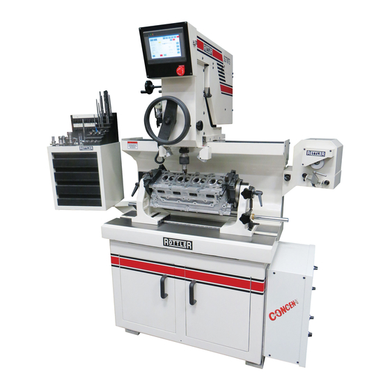
Section 1 Introduction SG7MTS Manual Description The SG7MTS uses the same proven fixed carbide pilot tooling as SG7M but now has a front mount steering wheel for spindle downfeed. The machine have 2 modes of operation: MANUALMATIC – a brand new concept has been added to these machines which should increase productivity by 30-50%. -
Page 8: Limited Warranty
Should a product not be as warranted, Rottler sole obligation shall be, at its option, to repair, correct or replace the product or to refund the amounts paid for the Product upon its return to a location designated by Rottler. -
Page 9: Online Documentation Access
SG7MTS Manual Online Documentation Access Online documentation for machines and optional equipment can be accessed at the Rottler website. To access documentation open your browser and navigate to https://www.rottlermfg.com. Scroll to the bottom of the page and under the Owner Resources title click the type of documentation you want to access. - Page 10 Section 1 Introduction SG7MTS Manual www.rottlermfg.com...
- Page 11 Section 2 Installation SG7MTS Manual INSTALLATION Contents INSTALLATION REPORT .....................2-2 Installation Procedure ....................2-6 Location ..........................2-6 Unpacking and Lifting ......................2-6 Positioning the Machine ...................... 2-6 Removing Shipping Brackets ....................2-7 Leveling the Machine ......................2-8 Air Supply ..........................2-9 Air Adjustments ........................
- Page 12 Section 2 Installation SG7MTS Manual ATTENTION OWNER/BUSINESS MANAGER To validate the warranty on your new Rottler machine, please be sure to sign the installation report after the installation technician has installed the machine and verified the machine is operating correctly and given the operators operation and maintenance training.
-
Page 13: Installation Report
L1 to ground _________VAC L2 to ground __________VAC. Make sure all electrical equipment has the proper overload protection. The SG7MTS should have a stable power supply to prevent damage and uncontrolled movement of the machine. Neutral and machine ground are not the same thing. You should measure an open circuit between Neutral and ground. - Page 14 INSTRUCTING THE OPERATOR: Note: Rotter employees and representatives per company policy are not permitted to provide end user of Rottler equipment with any OEM specifications for the workpiece that is created by end user using Rottler equipment. ______Using the operating manual as a guide explain the function of all buttons.
- Page 15 Rottler equipment. It is the responsibility of the end user of Rottler equipment to determine the final dimensions and finishes of the workpiece that they are working on. Any information regarding final dimensions and...
- Page 16 Section 2 Installation SG7MTS Manual www.rottlermfg.com...
-
Page 17: Installation Procedure
Installation Procedure Location The productivity of the SG7MTS will depend a great deal on the proper initial installation. Pay particular attention to the means by which work pieces are lifted into and out of the machine as well as the material handling to and from other operations in your shop. -
Page 18: Removing Shipping Brackets
Section 2 Installation SG7MTS Manual Removing Shipping Brackets Before leveling the machine, loosen and remove the all shipping brackets and bolts. (Figures 1 – 5) www.rottlermfg.com... -
Page 19: Leveling The Machine
Section 2 Installation SG7MTS Manual Leveling the Machine Use required machinist level. (Starret 98 or better). NOTE: Rotate Level 180º to check that Level is properly adjusted. If Level does not read same in both directions, recalibrate level. Use the level on the upper float surface, level the machine as precisely as possible, front to back and side to side. -
Page 20: Air Supply
Section 2 Installation SG7MTS Manual Air Supply It is very important the air source for the SG7MTS machine be moisture free. Water and oil in the line will result in early cylinder and valve failure. The factory recommends installing a water trap at the machine. -
Page 21: Power Supply
Section 2 Installation 2-10 SG7MTS Manual Power Supply This machine has the following power requirements: • 208 to 240 VAC • Single Phase Power • 50 or 60 Hz • 15 Amps See illustration below for correct connection of incoming power. Measured power at the machine’s main breaker must be within the required range listed above. -
Page 22: Grounding
Section 2 Installation 2-11 SG7MTS Manual Grounding The machine requires a good earth ground. The grounding conductor from the incoming power source must be connected to the grounding block located inside of the electrical cabinet. A ground rod installed in addition to the electrical service grounding conductor is permitted, but must be connected directly to the grounding block inside of the electrical cabinet. - Page 23 Section 3 Safety SG7MTS Manual SAFETY Contents Safety Information .......................3-1 Safety Instructions for Machine Use .................. 3-1 Electrical Power ......................3-3 Machine Operator ......................3-4 Emergency Procedure ......................3-4 www.rottlermfg.com...
-
Page 24: Safety Information
Section 3 Safety SG7MTS Manual Safety Information For Your Own Safety Read This Instruction Manual Before Operating This Machine. This is the safety alert symbol. It is used to alert you to potential personal injury hazards. Obey all safety messages that follow this symbol to avoid possible injury or death. - Page 25 Section 3 Safety SG7MTS Manual WEAR THE PROPER APPAREL. DO NOT wear loose clothing, gloves, rings, bracelets, or other jewelry which may get caught in moving parts. Non-Slip safety shoes are recommended. Wear protective hair covering to contain long hair.
-
Page 26: Electrical Power
Use only Rottler replacement parts and accessories; otherwise, warranty will be null and void. Misuse: Do not use the machine for other than its intended use. If used for other purposes, Rottler Manufacturing disclaims any real or implied warranty and holds itself harmless for any injury or loss that may result from such use. -
Page 27: Machine Operator
SG7MTS Manual Machine Operator The operator of the SG7MTS should be a skilled machinist craftsman who is well versed in the caution, care, and knowledge required to safely operate metal cutting tools. If the operator is not a skilled machinist he/she must pay strict attention to the Operating Instructions outlined in this manual, and get instruction from a qualified machinist in both production and operation of this machine. - Page 28 Section 3 Safety SG7MTS Manual www.rottlermfg.com...
- Page 29 Section 4 Control Definitions SG7MTS Manual CONTROL DEFINITIONS Left Side Controls www.rottlermfg.com...
- Page 30 Section 4 Control Definitions SG7MTS Manual Right Side Controls www.rottlermfg.com...
- Page 31 Aligning Spindle to Work .........................5-9 Changing the Spindle Adapters .......................5-9 Installing the Spherical self Aligning Toolholder ................5-9 Fine Feed Engagement ........................5-9 Rottler SG7MTS MANUALMATIC Touch Screen Control Panel ......5-10 Safety Tips Before Machining ................... 5-10 Operation ..........................5-11 Buttons ............................5-12 MANUALMATIC Operation ....................5-12 MANUAL ..........................
- Page 32 Shank Diameter ..........................5-18 Extended Length (EL) Pilots ......................5-18 Modular Carbide Centralizing Pilot System for Valve Guides Over 0.875” (22.23mm) 5-19 Rottler Six and One Instructions ................5-20 Adjusting the Square Carbide Inserts ................5-23 Cutting Small Diameter Valve Seats ................5-24 Tooling for Counterboring Small Diameter Valve Seat Pockets ......5-25 6 mm Pilots Boring Combos .....................
-
Page 33: Operating Instructions
Mount tool sharpener on right hand side of machine using the cap screw provided with machine. Sharpening the Rottler form Carbide bits, consists of restoring the tool cutting angle by grinding the face. To sharpen the carbide bit must be fitted on the bit holder also fitted on the tool holder. -
Page 34: Mounting Cylinder Heads
Section 5 Operating Instructions SG7MTS Manual Mounting Cylinder Heads 360 Degree Rollover Fixtures Initial clamp height adjustments to the head trunnions can be accomplished by measuring the head thickness then raising the turning clamping block assembly to the appropriate height using the clamping block acme screws. -
Page 35: Overhead Cam C Clamp System
Section 5 Operating Instructions SG7MTS Manual Overhead Cam C Clamp System Using 10mm Allen wrench, remove the existing lower fixed plate on the 360 degree fixture (left and right) Install the C Clamp, you must use the two bolts included with the fixture and make sure is good and tight The cylinder head gasket surface must be against the machined surface of the U Clamp Fixture;... - Page 36 Section 5 Operating Instructions SG7MTS Manual The Quick-Clamp frame is mounted between the trunnions and clamped using the clamping plates. (See Pictures) The cylinder head is then held to the frame with the swivel clamp assemblies through the appropriate head bolt holes or used the standard clamp plates.
-
Page 37: Alignment And Setup
Section 5 Operating Instructions SG7MTS Manual Alignment and Setup Alignment and setup applies to both the cylinder head and the machine’s floating head. The goal is to get perfectly align to the spindle centerline of the area of the head to be machined. Most machining operations on cylinder heads use the valve guide centerline as the reference point so we will use that as an example. -
Page 38: Left To Right Alignment
Section 5 Operating Instructions SG7MTS Manual Lightly tighten the lock levers on the supports to remove any play. Now tighten the clamp on the fine adjustment screw. Turn the adjustment knob to achieve the exact reading that was observed on the leveling post. -
Page 39: Three Angle Seat Cutting
The capacity of the Rottler SG80MTS associated with a complete tooling range allow working on seats of diameters between 14 and 120 millimeters (0.55’’- 4.7’’). Three tooling ranges are possible: 1) For seats diameters between 14 and 25 mm ( 0.55’’- 1’’): tool holder BH600R1 and Mini tip holder... -
Page 40: Checking Valve Seat Concentricity
Section 5 Operating Instructions SG7MTS Manual Checking Valve Seat Concentricity Make sure pilot and valve seat to be measured are free from dust, burrs, etc. A drop of oil or similar lubricant on valve seat will aid measuring. Loosen brass locking screw and lower dial gauge down over pilot. -
Page 41: Machining Valve Seats And Counter Boring
Installing the Spherical self Aligning Toolholder Once the spring free adapter is in the spindle, fit the Rottler Spherical Self aligning Tool holder assembly into the spindle adapter. Make sure to align the locator pins before you fit it into the spindle adapter and push it until you feel it lock. -
Page 42: Rottler Sg7Mts Manualmatic Touch Screen Control Panel
Section 5 Operating Instructions 5-10 SG7MTS Manual Rottler SG7MTS MANUALMATIC Touch Screen Control Panel Safety Tips Before Machining • Always wear proper Safety Items (such as safety glasses and other personal safety equipment as necessary or required). • Never wear loose fitting clothes or jewelry while working on or around Machine. -
Page 43: Operation
Section 5 Operating Instructions 5-11 SG7MTS Manual Operation Make sure E Stop is in. Flip switch on Electrical enclosure to ON (up) position, wait for screen to boot up, this may take a few seconds. This is the screen that will appear Tap MANUALMATIC for auto mode. -
Page 44: Buttons
Section 5 Operating Instructions 5-12 SG7MTS Manual Buttons BACK - goes 1 page back. VERTICAL ZERO - tap the SET button to set the vertical spindle height. VERTICAL POSITION - height spindle is at from VERTICAL ZERO height set. SPINDLE RPM - tap the box and a keyboard will pop up, enter RPM you would like to run and tap enter. -
Page 45: Manual
Section 5 Operating Instructions 5-13 SG7MTS Manual MANUAL Buttons BACK - goes 1 page back. VERTICAL ZERO - tap the SET button to set the vertical spindle height. VERTICAL POSITION - height spindle is at from VERTICAL ZERO height set. -
Page 46: Seat Machining Suggested Rpm Chart
At this point, the spindle and work head should be level according to the position of the cylinder head. Fit the Rottler Tool Holder and pilot assembly into the spindle cone; make sure to align the locator pins before you fit it into the spindle adapter and push it until you feel that is lock. -
Page 47: Changing Language
Section 5 Operating Instructions 5-15 SG7MTS Manual Changing Language Press the screen in the lower right hand corner, then press the screen in the upper right hand corner to bring up the Machine Settings screen. Be sure to press the screen with your finger and not just tap it. - Page 48 Section 5 Operating Instructions 5-16 SG7MTS Manual Press the Language Select button. Machine Settings Centering Timer Save (seconds) Back Changes 2.000 Variable Finish Acceleration (RPM/sec) Centering Timer 2 (seconds) 1.500 1000 Encoder VARIABLE RPM English Normal ENABLED Cursor Language Break in...
- Page 49 Section 5 Operating Instructions 5-17 SG7MTS Manual Confirm that the language you have selected is indicated and then restart the machine for the change to take effect. Turn the main power switch located on the electrical cabi- net off and then back on to restart the machine.
-
Page 50: Unipilot Centralizing Pilots
UCP0700 (0.2756”). Shank Diameter The part of the pilot that fits inside the tool holder is referred to as the shank. Rottler offers three different shank sizes (6.00mm, 9.52mm, and 20.00mm). For longest tool life and best seat cutting results, the shank needs to go as far as possible inside the tool holder when cutting valve seats or boring out valve seat housings. -
Page 51: Modular Carbide Centralizing Pilot System For Valve Guides Over 0.875" (22.23Mm)
Modular Carbide Centralizing Pilot System for Valve Guides Over 0.875” (22.23mm) Rottler also offers a modular carbide centralizing pilot system for very large engine applications. This system is versatile because it allows you to use different size sleeves, which are adjustable for different lengths, for different applications while using only one pilot. -
Page 52: Rottler Six And One Instructions
Section 5 Operating Instructions 5-20 SG7MTS Manual Rottler Six and One Instructions www.rottlermfg.com... - Page 53 Section 5 Operating Instructions 5-21 SG7MTS Manual www.rottlermfg.com...
- Page 54 Section 5 Operating Instructions 5-22 SG7MTS Manual www.rottlermfg.com...
-
Page 55: Adjusting The Square Carbide Inserts
Section 5 Operating Instructions 5-23 SG7MTS Manual Adjusting the Square Carbide Inserts • The micrometer should be used. • Set the Digital micrometer (BM) according to the valve seat insert diameter and the required interference. • Slide the tool holder without the pilot on the micrometer. -
Page 56: Cutting Small Diameter Valve Seats
Section 5 Operating Instructions 5-24 SG7MTS Manual Cutting Small Diameter Valve Seats The UPT5200 adapter has a set screw as shown in photo below – push pilot all the way into the UPT5200 and tighten set screw to hold pilot inside the UPT5200. Install the Tip Holder TH1999, adjust diameter, release set screw, and remove pilot. -
Page 57: Tooling For Counterboring Small Diameter Valve Seat Pockets
Bore diameter: 1.270” – 1.580” (32.26 mm – 40.15 Bore diameter: 1.000” – 1.280” (25.42 mm – 32.51 Rottler can also provide Fixed Milling Heads to cut valve seat pockets. They are available in fixed diameters from 1.000” to 2.250” in .0625” increments... - Page 58 Section 5 Operating Instructions 5-26 SG7MTS Manual www.rottlermfg.com...
- Page 59 Section 6 Maintenance SG7MTS Manual MAINTENANCE Contents Maintenance .........................6-1 Quick Reference Lubrication Chart ..................6-1 Preventative Maintenance Quick Reference Chart ............6-1 Air Adjustments ........................6-2 Float ..............................6-2 Float surfaces ........................6-2 Calibrating the Digital Level ....................6-3 Adjusting And Aligning The Outer Spindle On SG Models ..........6-4 Level Pin Setting ........................
-
Page 60: Maintenance
Section 6 Maintenance SG7MTS Manual Maintenance Quick Reference Lubrication Chart Refer to the maintenance section in the manual for lubrication location points and instruction. Assembly Frequency Lube Operation R e c o m m e n d e d Date Serviced... -
Page 61: Air Adjustments
Section 6 Maintenance SG7MTS Manual All floating surfaces should be dry and clean do not oil the surfaces, oil will cause the work heat not to float properly. Air Adjustments Float The float regulator is located at the right rear of the main base on the bottom. -
Page 62: Calibrating The Digital Level
Section 6 Maintenance SG7MTS Manual Calibrating the Digital Level NOTE: Even though the level has been carefully calibrated at the factory, it is a good idea to recheck calibration before putting the machine into service. In the event that the level is dropped or handled roughly then the following recalibration methods should be implemented. -
Page 63: Adjusting And Aligning The Outer Spindle On Sg Models
Section 6 Maintenance SG7MTS Manual Adjusting And Aligning The Outer Spindle On SG Models There are 2 brass guide shoes located on the guide plate on top of the spindle that align the rack gear on the back of the spindle with the pinion gear that moves the spindle up and down. - Page 64 Section 6 Maintenance SG7MTS Manual Adjusting outer spindle clearance. Loosen the 4 lock bolts. Loosen the 4 adjusting set screws. Clean outer spindle and lubricate – add a few drops of oil to a clean cloth and wipe outer spindle.
-
Page 65: Level Pin Setting
Section 6 Maintenance SG7MTS Manual Level Pin Setting www.rottlermfg.com... -
Page 66: Linear Scale Setting
Section 6 Maintenance SG7MTS Manual Linear Scale Setting www.rottlermfg.com... - Page 67 Section 7 Troubleshooting SG7MTS Manual TROUBLESHOOTING Contents Troubleshooting ......................7-1 SG Fault and Error Codes ...................7-3 www.rottlermfg.com...
- Page 68 Section 7 Troubleshooting SG7MTS Manual Troubleshooting Problem Possible Cause Solution Workhead base Insufficient air pressure Set air pressure of supplied line should be does not float minimum 85 PSI ( 6 Bars) Clamping plate does not drop Take the workhead to one end of the of the...
- Page 69 Section 7 Troubleshooting SG7MTS Manual Problem Possible Cause Solution Eccentricity Problems Machine is not level Level machine per instructions in when Cutting Three Angle Installation section of this manual Seats Workhead is not floating Be sure that the work head and main...
- Page 70 Section 7 Troubleshooting SG7MTS Manual Problem Possible Cause Solution Eccentricity Problems when Worn or improperly selected pilot Check pilot for wear and straightness Cutting Three Angle Seats Dull or damaged cutter insert Replace insert Incorrect pilot selection Follow directions in manual for...
- Page 71 Section 7 Troubleshooting SG7MTS Manual Overtorque Detection 2 High Slip Braking Overload Dynamic Braking Transistor External Fault 1, input terminal S1 External Fault 2, input terminal S2 External Fault at input terminal S3 External Fault at input terminal S4 External Fault at input terminal S5...
- Page 72 Section 7 Troubleshooting SG7MTS Manual CPF21 Hardware fault at communication start up CPF22 A/D Conversion Fault CPF23 PWM Feedback Fault CPF24 Drive capacity signal fault oFA00 Option compatibility error oFA01 Option not properly connected oFA03 Option Self-diagnostics Error oFA04 Option Flash Write Mode Error...
- Page 73 Section 7 Troubleshooting SG7MTS Manual Mechanical Weakening Detection 2 dWAL DriveWorksEZ Alarm RT4 Error Codes Description failed communication to display boardd no motor voltage (blown fuse) no motor current (lost motor conn) over current >6.8 amps (short) over current, >4.5 amp for 2 sec (slow) over current >10 amp for 1/100 sec (fast)
- Page 74 Section 7 Troubleshooting SG7MTS Manual www.rottlermfg.com...
- Page 75 TRANSMISSION ASSEMBLY - PARTS DESCRIPTION ..............8-12 HEAD SUPPORT ASSEMBLY..................... 8-14 HEAD SUPPORT ASSEMBLY - PARTS DESCRIPTION ..............8-15 RBHAR1KIT Repair Kit for RBHAR1 ................. 8-17 RBHAR40UPCKIT Repair Kit for RBHAR40UPT .............. 8-18 SG7MTS Pneumatic Drawing .................... 8-19 DECIMAL TO METRIC CONVERSION CHART ..............8-20 www.rottlermfg.com...
-
Page 76: Machine Parts
Section 8 Machine Parts SG7MTS Manual Machine Parts Consumable Parts REFERENCE DESCRIPTION SLEEVE R1 Spindle adapter replacement sleeve Diamond Wheel Cutting Bit Sharpener replacement Wheel (3.000" Diameter OD by BSW002 .375" ID) PRW600PIN Replaceable Pins for PRW600 Pilot Removable wrench tool... -
Page 77: Carbide Inserts
Section 8 Machine Parts SG7MTS Manual Carbide Inserts See Carbide Insert Catalog for a complete list of Insert Profiles available from Rottler Manufacturing. Special Profiles Special Profile Cutter Inserts can be manufactured to your exact specifications and can include a combination of angles and radius blends. -
Page 78: Cabinet Table & Riser Assembly
Section 8 Machine Parts SG7MTS Manual CABINET TABLE & RISER ASSEMBLY www.rottlermfg.com... -
Page 79: Cabinet Table & Riser Assembly Parts Description
Section 8 Machine Parts SG7MTS Manual CABINET TABLE & RISER ASSEMBLY PARTS DESCRIPTION www.rottlermfg.com... -
Page 80: Base Assembly
Section 8 Machine Parts SG7MTS Manual BASE ASSEMBLY www.rottlermfg.com... -
Page 81: Base Assembly - Parts Description
Section 8 Machine Parts SG7MTS Manual BASE ASSEMBLY - PARTS DESCRIPTION www.rottlermfg.com... - Page 82 Section 8 Machine Parts SG7MTS Manual www.rottlermfg.com...
-
Page 83: Spindle Assembly
Section 8 Machine Parts SG7MTS Manual SPINDLE ASSEMBLY www.rottlermfg.com... -
Page 84: Spindle Assembly - Parts Description
Section 8 Machine Parts SG7MTS Manual SPINDLE ASSEMBLY - PARTS DESCRIPTION www.rottlermfg.com... - Page 85 Section 8 Machine Parts 8-10 SG7MTS Manual www.rottlermfg.com...
-
Page 86: Transmission Assembly
Section 8 Machine Parts 8-11 SG7MTS Manual TRANSMISSION ASSEMBLY www.rottlermfg.com... -
Page 87: Transmission Assembly - Parts Description
Section 8 Machine Parts 8-12 SG7MTS Manual TRANSMISSION ASSEMBLY - PARTS DESCRIPTION www.rottlermfg.com... - Page 88 Section 8 Machine Parts 8-13 SG7MTS Manual www.rottlermfg.com...
-
Page 89: Head Support Assembly
Section 8 Machine Parts 8-14 SG7MTS Manual HEAD SUPPORT ASSEMBLY www.rottlermfg.com... -
Page 90: Head Support Assembly - Parts Description
Section 8 Machine Parts 8-15 SG7MTS Manual HEAD SUPPORT ASSEMBLY - PARTS DESCRIPTION www.rottlermfg.com... - Page 91 Section 8 Machine Parts 8-16 SG7MTS Manual www.rottlermfg.com...
-
Page 92: Rbhar1Kit Repair Kit For Rbhar1
Section 8 Machine Parts 8-17 SG7MTS Manual RBHAR1KIT Repair Kit for RBHAR1 Item Part # Description Quantity RBHAR1COL Collar 555-19-19 Stop Screw 555-19-20 Dog Point Screw 555-19-21 Ball Point 555-19-22 Detent 555-19-23 Ball Seat 555-19-24 Spring 555-19-25 Ball (4mm) www.rottlermfg.com... -
Page 93: Rbhar40Upckit Repair Kit For Rbhar40Upt
Section 8 Machine Parts 8-18 SG7MTS Manual RBHAR40UPCKIT Repair Kit for RBHAR40UPT Item Part # Description Quantity RBHAR40UPCCOL Collar 555-19-19 Stop Screw 555-19-20 Dog Point Screw 555-19-21 Ball Point 555-19-22 Detent 555-19-23 Ball Seat 555-19-24 Spring 555-19-25 Ball (4mm) www.rottlermfg.com... -
Page 94: Sg7Mts Pneumatic Drawing
Section 8 Machine Parts 8-19 SG7MTS Manual SG7MTS Pneumatic Drawing www.rottlermfg.com... -
Page 95: Decimal To Metric Conversion Chart
Section 8 Machine Parts 8-20 SG7MTS Manual DECIMAL TO METRIC CONVERSION CHART www.rottlermfg.com... - Page 96 Section 8 Machine Parts 8-21 SG7MTS Manual www.rottlermfg.com...
- Page 97 Section 9 Options SG7MTS Manual OPTIONS Optional Equipment Optional Equipment Catalog and Parts Manual are located on the Manual CD shipped with machine. www.rottlermfg.com...
- Page 98 Section 9 Options SG7MTS Manual www.rottlermfg.com...
- Page 99 Other substances and materials are used in the manufacture, testing, and shipping of this machine. A complete list of the Safety Data Sheets of substances and materials used by Rottler Manufacturing during manufacturing, testing, and shipping is located on the Manual flash drive shipped with the machine.
- Page 100 Section 10 Safety Data Sheets 10-2 SG7MTS Manual Safety Data Sheet According to OSHA HCS 2012 (29 CFR 1910.1200), Health Canada HPR (SOR/2015-17), and Mexico NOM-018-STPS-2015 SECTION 1: Identification Multi-Way Oil HD Product Identifier Other means of identification Phillips 66 Multi-Way Oil HD 32...
- Page 101 Section 10 Safety Data Sheets 10-3 SG7MTS Manual LBPH817776 - Multi-Way Oil HD Page 2/6 Issue Date: 16-Apr-2018 Status: FINAL _ _ _ _ _ _ _ _ _ _ _ _ _ _ _ _ _ _ _ _ _ _ _ _ _ _ _ _ _ _ _ _ _ _ _ _ _ _ _ _ _ _ _ _ _ _ _ _ _ _ _ _ _ _ _ _ _ _ _ _ _ _ _ _ _ _ _ _ _ Inhalation: First aid is not normally required.
- Page 102 Section 10 Safety Data Sheets 10-4 SG7MTS Manual LBPH817776 - Multi-Way Oil HD Page 3/6 Issue Date: 16-Apr-2018 Status: FINAL _ _ _ _ _ _ _ _ _ _ _ _ _ _ _ _ _ _ _ _ _ _ _ _ _ _ _ _ _ _ _ _ _ _ _ _ _ _ _ _ _ _ _ _ _ _ _ _ _ _ _ _ _ _ _ _ _ _ _ _ _ _ _ _ _ _ _ _ _ inert material such as sand or vermiculite, and place in suitable container for disposal.
- Page 103 Section 10 Safety Data Sheets 10-5 SG7MTS Manual LBPH817776 - Multi-Way Oil HD Page 4/6 Issue Date: 16-Apr-2018 Status: FINAL _ _ _ _ _ _ _ _ _ _ _ _ _ _ _ _ _ _ _ _ _ _ _ _ _ _ _ _ _ _ _ _ _ _ _ _ _ _ _ _ _ _ _ _ _ _ _ _ _ _ _ _ _ _ _ _ _ _ _ _ _ _ _ _ _ _ _ _ _ deficient (less than 19.5 percent oxygen) situations, or under conditions that are immediately dangerous to life and health (IDLH).
- Page 104 Section 10 Safety Data Sheets 10-6 SG7MTS Manual LBPH817776 - Multi-Way Oil HD Page 5/6 Issue Date: 16-Apr-2018 Status: FINAL _ _ _ _ _ _ _ _ _ _ _ _ _ _ _ _ _ _ _ _ _ _ _ _ _ _ _ _ _ _ _ _ _ _ _ _ _ _ _ _ _ _ _ _ _ _ _ _ _ _ _ _ _ _ _ _ _ _ _ _ _ _ _ _ _ _ _ _ _ Specific Target Organ Toxicity (Single Exposure): No information available on the mixture, however none of the components have been classified for target organ toxicity (or are below the concentration threshold for classification).
- Page 105 Section 10 Safety Data Sheets 10-7 SG7MTS Manual LBPH817776 - Multi-Way Oil HD Page 6/6 Issue Date: 16-Apr-2018 Status: FINAL _ _ _ _ _ _ _ _ _ _ _ _ _ _ _ _ _ _ _ _ _ _ _ _ _ _ _ _ _ _ _ _ _ _ _ _ _ _ _ _ _ _ _ _ _ _ _ _ _ _ _ _ _ _ _ _ _ _ _ _ _ _ _ _ _ _ _ _ _...
- Page 106 Section 10 Safety Data Sheets 10-8 SG7MTS Manual Safety Data Sheet According to OSHA HCS 2012 (29 CFR 1910.1200), Health Canada HPR (SOR/2015-17), and Mexico NOM-018-STPS-2015 SECTION 1: Identification Alco Super-Lube Multi-Purpose EP-0 Grease Product Identifier Code 829364 Relevant identified uses...
- Page 107 Section 10 Safety Data Sheets 10-9 SG7MTS Manual 829364 - Alco Super-Lube Multi-Purpose EP-0 Grease Page 2/6 Issue Date: 02-May-2017 Status: FINAL _ _ _ _ _ _ _ _ _ _ _ _ _ _ _ _ _ _ _ _ _ _ _ _ _ _ _ _ _ _ _ _ _ _ _ _ _ _ _ _ _ _ _ _ _ _ _ _ _ _ _ _ _ _ _ _ _ _ _ _ _ _ _ _ _ _ _ _ _ Inhalation: First aid is not normally required.
- Page 108 Section 10 Safety Data Sheets 10-10 SG7MTS Manual 829364 - Alco Super-Lube Multi-Purpose EP-0 Grease Page 3/6 Issue Date: 02-May-2017 Status: FINAL _ _ _ _ _ _ _ _ _ _ _ _ _ _ _ _ _ _ _ _ _ _ _ _ _ _ _ _ _ _ _ _ _ _ _ _ _ _ _ _ _ _ _ _ _ _ _ _ _ _ _ _ _ _ _ _ _ _ _ _ _ _ _ _ _ _ _ _ _ Methods and material for containment and cleaning up: Notify relevant authorities in accordance with all applicable regulations.
- Page 109 Section 10 Safety Data Sheets 10-11 SG7MTS Manual 829364 - Alco Super-Lube Multi-Purpose EP-0 Grease Page 4/6 Issue Date: 02-May-2017 Status: FINAL _ _ _ _ _ _ _ _ _ _ _ _ _ _ _ _ _ _ _ _ _ _ _ _ _ _ _ _ _ _ _ _ _ _ _ _ _ _ _ _ _ _ _ _ _ _ _ _ _ _ _ _ _ _ _ _ _ _ _ _ _ _ _ _ _ _ _ _ _ SECTION 9: Physical and chemical properties Note: Unless otherwise stated, values are determined at 20°C (68°F) and 760 mm Hg (1 atm).
- Page 110 Section 10 Safety Data Sheets 10-12 SG7MTS Manual 829364 - Alco Super-Lube Multi-Purpose EP-0 Grease Page 5/6 Issue Date: 02-May-2017 Status: FINAL _ _ _ _ _ _ _ _ _ _ _ _ _ _ _ _ _ _ _ _ _ _ _ _ _ _ _ _ _ _ _ _ _ _ _ _ _ _ _ _ _ _ _ _ _ _ _ _ _ _ _ _ _ _ _ _ _ _ _ _ _ _ _ _ _ _ _ _ _ carcinogenicity (or are below the concentration threshold for classification).
- Page 111 Section 10 Safety Data Sheets 10-13 SG7MTS Manual 829364 - Alco Super-Lube Multi-Purpose EP-0 Grease Page 6/6 Issue Date: 02-May-2017 Status: FINAL _ _ _ _ _ _ _ _ _ _ _ _ _ _ _ _ _ _ _ _ _ _ _ _ _ _ _ _ _ _ _ _ _ _ _ _ _ _ _ _ _ _ _ _ _ _ _ _ _ _ _ _ _ _ _ _ _ _ _ _ _ _ _ _ _ _ _ _ _ This material does not contain any chemicals subject to the reporting requirements of SARA 302 and 40 CFR 372.
Need help?
Do you have a question about the SG7MTS and is the answer not in the manual?
Questions and answers