
Related Manuals for Levil Aviation BOM


Summary of Contents for Levil Aviation BOM
- Page 1 2018 D-0007 BOM (Broadcasting Outer Module) Company Standards LEVL AVIATION 1704 KENNEDY POINT, SUITE 1124 OVIEDO, FL 32765...
- Page 2 Code Number D-0005 This manual is the property of Levil Aviation. It may not be replicated in whole or in part or otherwise divulged without prior written consent from Levil Aviation. All printed and electronic copies and versions except the one electronically signed inside the Levil Aviation database, are considered unofficial copies and may be used for reference only.
- Page 3 Initial release Warranty Levil Aviation warrants this product to the original purchaser to be free from defects in material and workmanship for a period of one year from the date of the original purchase. The following are not covered: software, damage resulting from accident, neglect, misuse, fire, or flood, improper voltage supply or failure to follow operational guidelines supplied with this product.
-
Page 4: Table Of Contents
BOM (Broadcasting Outer Module) Company Standards Effective Date 12/6/17 Page 3 of 12 Document No. Revision Code Number D-0005 Table of Contents Compliance and Use ..........................4 Technical Specifications ........................4 Design Specifications ..........................5 Material Requirements ........................5 Design Requirement ........................6 Flammability Testing Requirements ..................... -
Page 5: Compliance And Use
D-0005 1. Compliance and Use The BOM meets the design and performance requirements of 14 CFR 21.137 and is produced under a quality system that satisfies the requirements of the FAA Policy number PS-AIR-21.8- 1602. The BOM is not TSO’d and is pending NORSEE Certification. Upon NORSEE Certification approval, the BOM will be approved for design and production for Aircraft Certified under 14 CFR 23 or earlier regulations. -
Page 6: Design Specifications
Table 1. Technical Specifications 3. Design Specifications 3.1 Material Requirements The outer housing of the BOM must use UV resistant and non-permeable materials including: a. Delrin and Aluminum-Alloy 6061. b. Assembly screws for the outer housing must be stainless steel. -
Page 7: Design Requirement
D-0005 3.2 Design Requirement All systems of the BOM must meet all the design parameters as set by the different system’s operational requirements and/or drawing specifications. Engineering drawings must include the information necessary to duplicate each product to comply with this standard. -
Page 8: Company Specifications
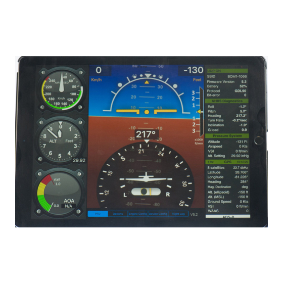
The BOM combines different avionic systems into one module and sends the information via Wi-Fi to a tablet. All systems of the BOM are individually tested to meet certain performance criteria and are then combined and tested as a whole system. The following diagram, shows the different systems that make up the BOM and how they all integrate with one another. -
Page 9: Ad-Ahrs
It is designed and manufactured by Levil Aviation, guaranteeing each individual board is calibrated to withstand extreme environmental conditions (turbulence, humidity, high- temperatures, etc.) The AHRS information is sent by the IMU Microprocessor to the BOM’s main Microprocessor which is then transmitted to a tablet via Wi-Fi and displayed accordingly. -
Page 10: Roll, Pitch And Yaw
AHRS inside the BOM. As a rule of thumb, one foot is recommended. However, this is not always possible, thus, the AHRS has internal algorithms that “learn” your aircraft configuration as you fly. -
Page 11: Vibration Sensor
0 to 320 kt. and the deviation after calibration cannot be more than ±3 kt. 9.2 Vibration Sensor The sensor is designed to aid the BOM determine when to wake up. The BOM is designed to turn ON with power input from the turbine, but since this process requires a minimum speed of 60Kts, the BOM will not start until after takeoff. -
Page 12: Position Source (Gps Or Glonass)
Latitude, Longitude, Geometric Altitude, Ground Speed, Track, Climb Rate UTC time. If the GPS/GLONASS source is not able to get a position fix, the BOM will continue to stream primary flight data (i.e. AHRS) since other systems are independent from GPS. -
Page 13: Power System
The BOM is self-powered and completely independent from the power of the aircraft or any of its systems. The BOM turns On and Off using a vibration sensor and it has an internal battery which is recharged using a turbine. The excess power of the turbine is dissipated to the nose and the heat keeps the nose free of ice.
Need help?
Do you have a question about the BOM and is the answer not in the manual?
Questions and answers