
Related Manuals for SMA WAGO-I/O-SYSTEM 750


Summary of Contents for SMA WAGO-I/O-SYSTEM 750
- Page 1 Installation Manual WAGO-I/O-SYSTEM 750 with SMA DATA MANAGER M ENGLISH EDMM-WAGO-IO-IA-en-11 | Version 1.1...
- Page 2 Legal Provisions The information contained in these documents is the property of SMA Solar Technology AG. No part of this document may be reproduced, stored in a retrieval system, or transmitted, in any form or by any means, be it electronic, mechanical, photographic, magnetic or otherwise, without the prior written permission of SMA Solar Technology AG.
-
Page 3: Table Of Contents
Connection to Data Manager M ........................36 Commissioning ..........................38 Connecting the WAGO-I/O-SYSTEM 750 with Data Manager M ............38 Assigning the IP address ..........................38 Configuring the WAGO-I/O-SYSTEM 750 via Data Manager M user interface........39 7.3.1 Device registration ............................39 Installation Manual... - Page 4 Table of Contents SMA Solar Technology AG 7.3.2 Selecting the device for configuring sensors ....................40 7.3.3 Defining the input and function for configuring sensors ................40 7.3.4 Defining the channel and scaling for grid management services ..............44 7.3.5 Displaying measured values locally on the Data Manager M Modbus server...........
-
Page 5: Information On This Document
Validity This document is valid for: • EDMM-10 (SMA Data Manager M) • WAGO-I/O-SYSTEM 750 configured for EDMM-10 (SMA order number: 115214-00.01) Target Group The tasks described in this document must only be performed by qualified persons. Qualified persons must have the following skills: •... -
Page 6: Typographies In The Document
1 Information on this Document SMA Solar Technology AG Symbol Explanation A problem that might occur ✖ Example Typographies in the Document Typography Example bold • Messages • Connect the insulated conductors to the terminals X703:1 to • Terminals X703:6. -
Page 7: Safety
2 Safety Intended Use The WAGO-I/O-SYSTEM 750 is used to receive digital and analog signals from sensors and output them to actuators. The WAGO-I/O-SYSTEM 750 and the assembled I/O modules were developed for a working environment that complies with the IP20 degree of protection. It is equipped with a finger guard and protection against solid foreign objects ≥... - Page 8 2 Safety SMA Solar Technology AG NOTICE Damage to the product due to condensation If the product is moved from a cold environment to a warm environment, condensation may form in the product. This can damage the product or impair its functionality.
- Page 9 2 Safety SMA Solar Technology AG Use of Ethernet devices Please observe the following information if you use Ethernet devices in your system: • Do not connect the control components and control networks with an open network such as the Internet.
-
Page 10: Scope Of Delivery
3 Scope of Delivery SMA Solar Technology AG 3 Scope of Delivery Check the scope of delivery for completeness and any externally visible damage. Contact your distributor if the scope of delivery is incomplete or damaged. Figure 1: Components included in the scope of delivery... -
Page 11: Product Overview
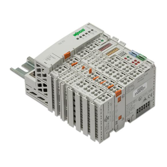
4 Product Overview WAGO-I/O-SYSTEM 750 The WAGO-I/O-SYSTEM 750 is a modular, fieldbus-independent input/output system (I/O system). The configuration consists of a fieldbus coupler, supply module, and the assembled I/O modules for any signal type. These I/O modules together make up the fieldbus node. The bus end terminal completes the fieldbus node and is required for correct operation. - Page 12 4 Product Overview SMA Solar Technology AG The interfaces can be connected to any Ethernet system. The data transfer rate and pin assignment are determined automatically. The IP address is assigned via DHCP by default. Alternatively, the address selection can be used to assign the last byte of the IP address as well as the use of a fixed IP address.
-
Page 13: Dc 24 V Supply Module
4 Product Overview SMA Solar Technology AG For the diagnostics of the different areas for the fieldbus coupler and fieldbus nodes, the LEDs can be divided into corresponding groups. Figure 4: Fieldbus coupler LEDs Position LED group Color Explanation Fieldbus status... -
Page 14: I/O Modules
For detailed information on evaluation of the LED statuses (see Section 4.8 "LED Signals", page 16). I/O modules Different sensors and actuators are connected to the WAGO-I/O-SYSTEM 750 via the I/O modules. Single-, multiple-, or fine-wire conductors can be connected via the CAGE CLAMP® connections. The terminal bus is responsible for communication between the fieldbus coupler/controller and the individual I/O modules. -
Page 15: Bus End Terminal 750-600
Hardware address (MAC ID) The WAGO-I/O-SYSTEM 750 has an internationally unique physical address: the MAC ID (Media Access Control Identity). The MAC ID is printed on a paper strip with two self-adhesive tear-off labels on the left side of the field bus coupler/ controller. -
Page 16: Led Signals
4 Product Overview SMA Solar Technology AG LED Signals LED signals of the fieldbus coupler The LEDs indicate the operating state of the fieldbus coupler or the entire fieldbus node. The LEDs are assigned to various diagnostic areas in groups. - Page 17 4 Product Overview SMA Solar Technology AG LED status Description Corrective measures Flashing red/green Self-test There is no operating voltage for the system. 1. Check the power supply. NS (network status) Green The fieldbus node is connected to the physi- cal network.
- Page 18 4 Product Overview SMA Solar Technology AG LED signals of the 4-channel analog input terminal Figure 9: LEDs of the 4-channel analog input terminal Channel Designation LED status Description Error AI 1 Normal operation Wire break, values outside of the permitted...
- Page 19 4 Product Overview SMA Solar Technology AG LED signals of the 8-channel DC 24 V analog input terminal Figure 11: LEDs of the 8-channel DC 24 V digital input terminal Channel Designation LED status Description A - H 1 - 8 Status DI 1 - 8...
- Page 20 4 Product Overview SMA Solar Technology AG LED signals of the 2/4-channel analog input terminal TempIN Figure 13: LEDs of the 2/4-channel analog input terminal TempIN Channel LED status Description System is not available, lack of or disturbed terminal bus communication (only when the...
- Page 21 4 Product Overview SMA Solar Technology AG Channel LED status Description No error Range violated (values too high or too low), short circuit or wire break Installation Manual EDMM-WAGO-IO-IA-en-11...
-
Page 22: Mounting
Properties of the mounting rail The WAGO-I/O-SYSTEM 750 can be directly snapped onto a mounting rail in accordance with EN 60175 (TS 35, DIN Rail 35). Please note that mounting rails can have different mechanical and electrical characteristics. To ensure optimal functioning, the following conditions must be observed: The material must be corrosion-resistant. -
Page 23: Mounting The Product On The Mounting Rail
Mounting the product on the mounting rail The WAGO-I/O-SYSTEM 750 comes pre-configured and is directly snapped onto the mounting rail as a complete unit. A tongue and groove system is used for secure positioning and connection. Automatic locking guarantees secure hold on the mounting rail. - Page 24 5 Mounting SMA Solar Technology AG • Press the product down onto the mounting rail from the top. ☑ The product snaps audibly into place. 2. Ensure that the product is securely in place. EDMM-WAGO-IO-IA-en-11 Installation Manual...
-
Page 25: Connection
6 Connection SMA Solar Technology AG 6 Connection Overview of the Connection Area Figure 15: Overview of the connection area Position Designation DC 24 V system supply DC 0 V system supply Fieldbus connection 2 x RJ-45 as a 2-port Ethernet switch Feed-in: DC 24 V field supply... -
Page 26: Information On Shielding
6 Connection SMA Solar Technology AG Procedure: 1. Use a suitable tool to unlock the CAGE CLAMP® in the opening above the connection. 2. Insert the conductor into the corresponding connection opening. 3. To lock the CAGE CLAMP®, remove the tool from the opening. -
Page 27: Voltage Supply Terminal
The fieldbus coupler and supply module are responsible for feeding-in the system and field voltage supply of the WAGO-I/O-SYSTEM 750. For components that work with low voltages, only SELV/PELV voltage sources can be used. To supply multiple components from a single voltage source, this voltage source must be designed in accordance with the strictest electrical safety requirements based on these components. -
Page 28: Power Supply Design
6 Connection SMA Solar Technology AG The WAGO-I/O-SYSTEM 750 requires a 24 V direct voltage for the system supply. The voltage is fed in via the supply module and is protected against reverse polarity. +24 V DC (-15 % / +20 %) -
Page 29: Connecting Different Components At The I/O Modules
6 Connection SMA Solar Technology AG 6.5.5 Connecting different components at the I/O modules Five I/O modules are available for connecting different components: • 8-channel DC 24 V digital input terminal • 8-channel DC 24 V digital output terminal • 2/4-channel analog input terminal 2 TempIN (PT100) •... -
Page 30: 8-Channel Dc 24 V Digital Output Terminal
6 Connection SMA Solar Technology AG DI 1 24 V DI 2 24 V DI 3 24 V +24 V + 24 V DI 4 24 V 10 nF DI 5 24 V DI 6 24 V DI 7 24 V... - Page 31 6 Connection SMA Solar Technology AG For detailed information on evaluation of the LED statuses (see Section 4.8 "LED Signals", page 16). Figure 20: Connections of the 8-channel DC 24 V digital output terminal Position Channel Connec- Designation Designation tion A - H...
-
Page 32: 2/4-Channel Analog Input Terminal (Tempin)
6 Connection SMA Solar Technology AG 6.5.5.3 2/4-channel analog input terminal (TempIN) The 2/4-channel analog input terminal (TempIN) evaluates two PT100 sensors. The resistance values are converted to temperature values. A microprocessor in the bus terminal linearizes the measured resistance values and converts them into a numerical value that is proportional to the temperature of the selected resistance sensor. -
Page 33: 4-Channel Analog Input Terminal 4 Ma To 20 Ma
6 Connection SMA Solar Technology AG +R3 +R4 Figure 25: Example connection of the 2/4-channel analog input terminal (TempIN) 6.5.5.4 4-channel analog input terminal 4 mA to 20 mA The 4-channel analog input terminal 4 mA to 20 mA has four input channels for field signals and processes signals of standard size from 4 mA to 20 mA. -
Page 34: 4-Channel Analog Output Terminal 0 Ma To 20 Ma
6 Connection SMA Solar Technology AG logic AI 1 AI 2 error 270 pF ground 24 V AI 3 AI 4 10 nF ground ground Figure 27: Circuitry of the 4-channel analog input terminal 4 mA to 20 mA Figure 28: Example connection of the 4-channel analog input terminal 4 mA to 20 mA 6.5.5.5... - Page 35 6 Connection SMA Solar Technology AG For detailed information on evaluation of the LED statuses (see Section 4.8 "LED Signals", page 16). Figure 29: Connections of the 4-channel analog output terminal 0 mA to 20 mA Position Channel Connec- Designation Designation tion AO 1...
-
Page 36: Connection To Data Manager M
6 Connection SMA Solar Technology AG Figure 31: Example connection of the 4-channel analog output terminal 0 mA to 20 mA 6.5.6 Connection to Data Manager M NOTICE Damage to the product due to incorrect connection • Only use devices with an Ethernet/RJ-45 connection in LANs. - Page 37 6 Connection SMA Solar Technology AG Position Signal Designation Not assigned Not assigned RD - Receive data - Not assigned Not assigned Installation Manual EDMM-WAGO-IO-IA-en-11...
-
Page 38: Commissioning
Connecting the WAGO-I/O-SYSTEM 750 with Data Manager M Reserving the IP address If the communication between the WAGO-I/O-SYSTEM 750 and Data Manager M works properly, the IP address must be permanently reserved for the WAGO-I/O-SYSTEM 750 in DHCP. If you have any questions, contact your administrator. Requirements: ☐... -
Page 39: Configuring The Wago-I/O-System 750 Via Data Manager M User Interface
☐ A router is connected to the system and, ideally, has Internet access. ☐ The WAGO-I/O-SYSTEM 750 is connected with Data Manager M via the Ethernet interface (RJ-45). Both Ethernet ports on the WAGO-I/O-SYSTEM 750 and on Data Manager M can be used for this purpose. Procedure: 1. -
Page 40: Selecting The Device For Configuring Sensors
Selecting the device for configuring sensors Requirements: ☐ The WAGO-I/O-SYSTEM 750 is in operation and registered as a new Modbus device in Data Manager M. ☐ During configuration, a signal from 4 mA to 20 mA must be present at the analog inputs. Procedure: 1. - Page 41 7 Commissioning SMA Solar Technology AG Procedure: 1. Log in to the user interface of Data Manager M. 2. Select the I/O configuration menu item in the Configuration menu. 3. Click the button to configure a new channel. 4. Determine whether the channel is an input or output channel.
- Page 42 7 Commissioning SMA Solar Technology AG Figure 35: Example configuration: solar irradiation EDMM-WAGO-IO-IA-en-11 Installation Manual...
- Page 43 7 Commissioning SMA Solar Technology AG Figure 36: Example configuration: wind speed Installation Manual EDMM-WAGO-IO-IA-en-11...
-
Page 44: Defining The Channel And Scaling For Grid Management Services
7 Commissioning SMA Solar Technology AG Figure 37: Example configuration: temperature input 6. Fill out the input fields and confirm with [Save]. 7. Select the Instantaneous values menu item in the Monitoring menu and check the information entered. The newly added channel should now appear in the list and display the current values. - Page 45 Procedure: 1. Log in to the user interface of Data Manager M. 2. Select the WAGO-I/O-SYSTEM 750 in the list view in the SELECT DEVICE menu under the name that was assigned during device configuration. 3. Select the I/O configuration menu item in the Configuration menu.
- Page 46 7 Commissioning SMA Solar Technology AG Figure 38: Example configuration 6. To create the channel as a setpoint source and as a percentage, select the Current input input and the Percent channel. 7. Fill out the input fields and confirm with [Save].
- Page 47 7 Commissioning SMA Solar Technology AG Figure 39: Example configuration 10. To create the current output as a power actual value, fill out the input fields and confirm with [Save]. 11. Review the added channels in the I/O configuration menu.
- Page 48 7 Commissioning SMA Solar Technology AG Figure 40: Example configuration 14. Fill out the input fields and click [Next]. 15. Follow the installation assistant steps and make the settings according to the specifications required by the grid operator and laid down in the standards.
-
Page 49: Displaying Measured Values Locally On The Data Manager M Modbus Server
7 Commissioning SMA Solar Technology AG 20. Select the Output channel that was previously configured in the I/O configuration and confirm with [Save]. 21. To assign additional actual values to the corresponding output channels, click the button. 7.3.5 Displaying measured values locally on the Data Manager M Modbus... - Page 50 7 Commissioning SMA Solar Technology AG 6. Select the settings for the device and confirm with [Save]. 7. Repeat the process to add additional sensors such as, for example, for cell temperature. 8. Check the added sensors in the SENSOR ASSIGNMENT menu.
-
Page 51: Troubleshooting
8 Troubleshooting SMA Solar Technology AG 8 Troubleshooting Fieldbus failure A fieldbus failure occurs if, for example, the master is switched off or the bus cable is interrupted. An error in the master can also result in a fieldbus failure. -
Page 52: Contact
Sunny Tripower, Sunny Highpower: for Netherlands: +31 30 2492 000 Luxemburg +49 561 9522‑1499 SMA Online Service Center: Luxembourg Monitoring Systems, SMA EV Charger: www.SMA-Service.com Nederland +49 561 9522‑2499 Česko SMA Service Partner TERMS a.s Hybrid Controller: +420 387 6 85 111 +49 561 9522-3199 Magyarország SMA Online Service Center: Sunny Island, Sunny Boy Storage, Slovensko www.SMA-Service.com Sunny Backup: +49 561 9522-399 Türkiye... - Page 53 +66 20598220 +562 2820 2101 Chile smaservice@spe.co.th Perú Service Partner for Utility: South Africa SMA Solar Technology South Africa Tirathai E & S Co., Ltd Pty Ltd. 516/1 Moo 4, Bangpoo Industrial Es- tate Cape Town Sukhumvit Road, T. Praksa, A. Muang 08600SUNNY 10280 Samutprakarn, Thailand (08600 78669)
- Page 54 www.SMA-Solar.com...
Need help?
Do you have a question about the WAGO-I/O-SYSTEM 750 and is the answer not in the manual?
Questions and answers