Table of Contents
Advertisement
Quick Links
Advertisement
Table of Contents

Related Manuals for Pride Mobility VR2


Summary of Contents for Pride Mobility VR2
- Page 1 Basic Operation Instructions...
- Page 2 Identification Key © Copyright 2020 INFMANU3354/Rev H/February 2020...
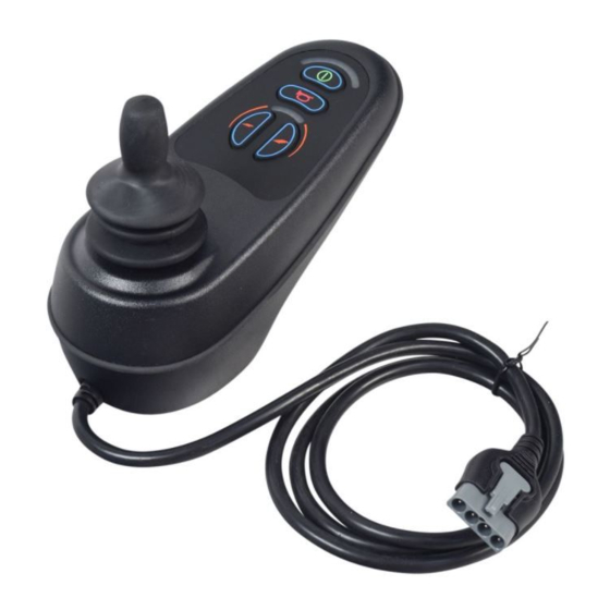
- Page 3 Identification Key Controller Battery Condition Meter On/Off Button Horn Button Maximum Speed Speed/Profile Profile Indicator Decrease Button Speed/Profile Charger Port Joystick Increase Button...
- Page 4 Identification Key...
- Page 5 Identification Key Controller Battery Condition Meter On/Off Button Horn Button Maximum Speed/ Speed/Profile Profile Indicator Decrease Button Mode LED Actuator Buttons Joystick Speed/Profile Charger Port Increase Button...
- Page 6 Identification Key...
- Page 7 Identification Key Controller Battery Condition Meter On/Off Button Horn Button Hazard Button Maximum Speed/ Profile Indicator Speed/Profile Mode LED Left Turn Indicator Button Decrease Button Joystick Actuator Button Right Turn Indicator Button Speed/Profile Light Button Charger Port Increase Button...
- Page 8 NOTE: This product is compliant with WEEE, RoHS, and REACH directives and requirements. NOTE: This product meets IPX4 classification (IEC 60529). NOTE: The VR2 Controller and its components are not made with natural rubber latex. Consult with the manufacturer regarding any after-market accessories.
-
Page 9: Table Of Contents
Table of Contents Label Information ..........................10 VR2 Controller ..........................11 Precautionary Guidelines ......................... 11 Operating the VR2 Controller ......................11 Controller Communication Connector .................... 13 Actuator Adjustment ......................... 13 Drive Profile Selection ........................14 Speed Adjustment ..........................14 Lock Mode ............................14 Sleep Mode ............................ -
Page 10: Label Information
Label Information Product Safety Symbols The symbols below are used on the power chair to identify warnings, mandatory actions, and prohibited actions. It is very important for you to read and understand them completely. Read and follow the information in the owner's manual. Avoid exposure to rain, snow, ice, salt, or standing water whenever possible. -
Page 11: Vr2 Controller
VR2 Controller The VR2 Controller is a fully programmable, modular electronic controller system that allows you to operate your power chair. It is designed to allow the user to have complete control over chair movement and speed. The controller has been pre-programmed to meet a typical user’s needs. The program is set using either a personal computer with software provided by the controller manufacturer or with a hand-held programmer, also provided by the controller manufacturer. - Page 12 You may use an off-board charger to charge your power chair batteries through the 3-pin socket located on the front of the VR2. If you use an off-board charger, the charger current should not exceed 8 amps. Contact your authorized Pride/Quantum Rehab Provider for more information.
-
Page 13: Controller Communication Connector
Actuator Adjustment The VR2 Controller can control two actuators using the actuator buttons and the joystick. The active actuator is indicated by an illuminated actuator LED. -
Page 14: Drive Profile Selection
Drive Profile Selection Your VR2 Controller may be programmed for up to five drive profiles that allow the system to be custom tailored to your environment. The selected profile is displayed by the maximum speed/profile indicator. NOTE: Drive profiles are set by your authorized Pride/Quantum Rehab Provider. Contact your authorized Pride/Quantum Rehab Provider to change a drive profile or change speed settings. -
Page 15: Sleep Mode
Sleep Mode The VR2 Controller features a sleep mode. Sleep mode is a built-in circuit that will automatically shut off the main power if the joystick is not moved in any direction for a period of time. This time factor is programmed into the controller. -
Page 16: Care And Maintenance
Fault Code Probably Cause Possible Solutions 1 Flash The batteries need charging. There is a Check the battery connections. If the bad connection to the batteries. battery connections are good, then try charging the batteries. 2 Flashes There is a bad connection on the left Check the left motor connections and motor. - Page 20 B.V. (Authorised EU Representative) 182 Susquehanna Avenue De Zwaan 3 Exeter, PA 18643-2694 1601 MS Enkhuizen Canada The Netherlands 5096 South Service Road www.pride-mobility.nl Beamsville, Ontario L0R 1B3 Italy Australia Via del Progresso-ang. Via del Lavoro 20-24 Apollo Drive Loc. Prato della Corte Hallam, Victoria 3803 00065 Fiano Romano (RM) www.pridemobility.com.au...
Need help?
Do you have a question about the VR2 and is the answer not in the manual?
Questions and answers