Table of Contents
Advertisement
Quick Links
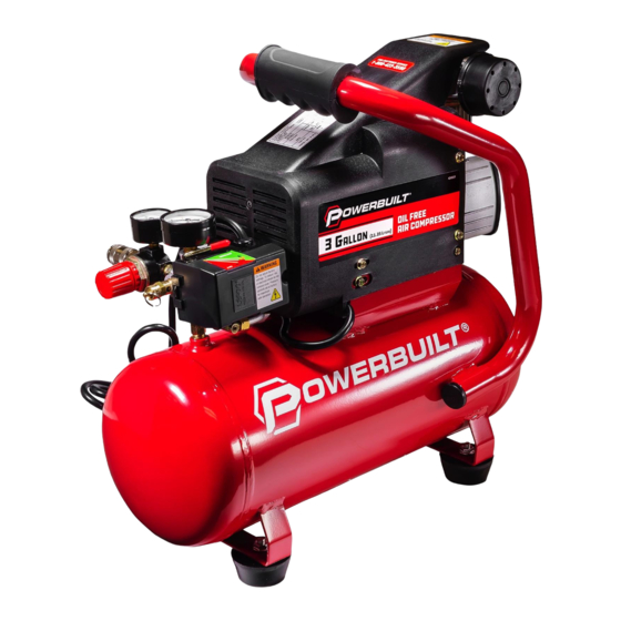
3 GALLON AIR COMPRESSOR
INSTRUCTION MANUAL
THIS MANUAL CONTAINS IMPORTANT INFORMATION REGARDING SAFETY, OPERATION, MAINTENANCE AND
STORAGE OF THIS PRODUCT. BEFORE USE, READ CAREFULLY AND UNDERSTAND ALL CAUTIONS, WARNINGS,
INSTRUCTIONS AND PRODUCT LABELS. FAILURE TO DO SO COULD RESULT IN SERIOUS PERSONAL INJURY
AND/OR PROPERTY DAMAGE.
IF YOU SHOULD HAVE ANY QUESTIONS OR EXPERIENCE A PROBLEM WITH YOUR SNAP-ON
PRODUCT, DO NOT RETURN THIS PRODUCT TO THE STORE. PLEASE CALL OUR CUSTOMER SERVICE
DEPARTMENT AT 1-800-423-3598. BEFORE YOU CALL, HAVE THE FOLLOWING INFORMATION AVAILABLE:
MODEL No., DATE PURCHASED AND STORE LOCATION. AN ALLTRADE REPRESENTATIVE CAN RESOLVE YOUR
PROBLEM OVER THE PHONE.
MODEL #240039
Advertisement
Table of Contents

Related Manuals for Powerbuilt 240039


Summary of Contents for Powerbuilt 240039
- Page 1 MODEL #240039 3 GALLON AIR COMPRESSOR INSTRUCTION MANUAL THIS MANUAL CONTAINS IMPORTANT INFORMATION REGARDING SAFETY, OPERATION, MAINTENANCE AND STORAGE OF THIS PRODUCT. BEFORE USE, READ CAREFULLY AND UNDERSTAND ALL CAUTIONS, WARNINGS, INSTRUCTIONS AND PRODUCT LABELS. FAILURE TO DO SO COULD RESULT IN SERIOUS PERSONAL INJURY AND/OR PROPERTY DAMAGE.
-
Page 2: Table Of Contents
TABLE OF CONTENTS CONGRATULATIONS ................... 1 SPECIFICATIONS ....................2 INTRODUCTION ....................2 SAFETY ALERT ....................3 RECOGNIZE SAFETY SYMBOLS, WORDS AND LABELS ......3 UNPACKING & INSPECTION ................4 SAFETY WARNINGS .................... 4-8 GENERAL SAFETY WARNINGS ..............4-8 INSTALLATION AND LOCATION ................. 8-9 GROUNDING INSTRUCTIONS ................ -
Page 3: Specifications
SPECIFICATIONS SPECIFICATIONS Two Pole Induction Motor 3450 RPM Power 120V, 60 Hz, 8.6 Amps Air Delivery 3.6 SCFM output @ 40 PSI 2.5 SCFM output @ 90 PSI Maximum Pressure 125 PSI Duty Cycle 1.5 Peak HP / 1 Running HP 3 Gallon (11.35 liter) Air Tank Oil Free Direct Drive Pump High Flow Regulators for Precision Air Flow Control... -
Page 4: Safety Alert
SAFETY ALERT Read and understand this entire instruction manual before attempting to assemble, install, operate or maintain this air compres- sor. Failure to comply with the instructions may result in serious personal injury and/or property damage! SAVE THESE INSTRUCTIONS FOR FUTURE REFERENCE. -
Page 5: Unpacking & Inspection
UNPACKING & INSPECTION See page 15 for detailed unpacking and installation procedures. After opening the carton, unpack your new air compressor and related parts & accessories. Please inspect it carefully for any damage that may have occurred during transit. Please check it against the photograph on carton. If any parts are missing, please contact our Consumer Helpline: 1-800-423-3598. - Page 6 Operating any tools or equipment under the influence of drugs, alcohol, or medication can cause personal injury to yourself and others. Wear proper apparel. Remove your jewelry before using air compressor. Do not wear loose clothing, necklaces, rings, bracelets, or other jewelry, which may get caught in mov- ing parts.
- Page 7 Always make sure the tool is in the OFF position and unplugged from the electrical receptacle when making adjustments, changing parts, or perform- ing any maintenance. Secure work. When possible, the use of clamps or a holding device is much safer than holding the work piece with your hands.
- Page 8 RISK OF BURSTING • Do not adjust regulator to result in output pressure greater than marked maximum pressure of attachment. If a regulator has not been installed, use only attachment rated at 200 PSI or higher. Do not weld on or repair tank — A DAMAGED TANK MUST BE REPLACED IMMEDIATELY.
-
Page 9: Installation And Location
RISK OF FLYING OBJECTS Do not direct compressed air stream at people or pets. The powerful compressed air stream can damage exposed skin and easily propel loose dirt and other small objects at high-speed, resulting in serious injury. Always wear eye protection that meets ANSI Z28.1 specifications. -
Page 10: Grounding Instructions
DO NOT place air compressor in an area: • Where there is evidence of oil or gas leaks. • Where flammable gas vapors or materials may be present. • Where air temperatures fall below 32ºF or exceed 104ºF. • Where extremely dirty air or water could be drawn into the air compressor. Serious injury or death may occur if electrical sparks from motor and pressure switch come in contact with flammable vapors, combustible dust, gases or other combustible materials. -
Page 11: Extension Cords
This product should be grounded. In the event of an electrical short circuit, grounding reduces the risk of electric shock by providing an escape wire for the electric current. This product is equipped with a cord having a grounding wire with an appropriate grounding plug. The plug must be plugged into an outlet that is properly installed and grounded in accordance with all local codes and ordinances. - Page 12 EXTENSION CORD LENGTH WIRE SIZE (AWG) Up to 25 Feet 26 to 50 Feet 51 to 100 Feet Do Not Use Use only extension cords that are intended for outdoor use. These cords are identified by a marking “ACCEPTABLE FOR USE WITH OUTDOOR APPLIANCES, STORE INDOORS WHEN NOT IN USE.”...
-
Page 13: Compressor Features
COMPRESSOR FEATURES (on other side of tank) CONTROLS AND COMPONENTS: 9. Air Tank Drain Valve 1. Air Pump (on other side of tank) 2. Automatic On/Off Pressure Switch 10. Air Intake Filter 3. Motor Shroud 11. Soft Grip Handle 4. Pressure Regulator Knob 12. - Page 14 COMPRESSOR FEATURES: 1. AIR PUMP: Oil less direct drive pump with cast-iron cylinder for durability. 2. AUTOMATIC ON/OFF PRESSURE SWITCH: This compressor is equipped with an automatic on/off pressure switch. The compressor will only run when the switch is in the ON/AUTO position.
- Page 15 9. AIR TANK DRAIN VALVE: Moisture is produced whenever air is compressed. It is critical to drain water from the air tank on this compressor frequently. If unit is used only occasionally, tank should be drained after each use and prior to the next use. To drain the tank, slowly open the tank drain fitting by turning clockwise.
-
Page 16: Operating The Air Compressor
OPERATING THE AIR COMPRESSOR Do not attach air hose, air tools or other air accessories to the air outlet until break-in procedure has been successfully completed. INITIAL SETUP / BREAK-IN PROCEDURE 1. Read and understand the entire instruction manual, including all safety warnings before setting up air compressor. -
Page 17: Startup
STARTUP 1. Before each startup, make sure the power switch is in the OFF position. 2. Place air compressor on a flat, level surface. 3. Slowly open tank drain valve to release pressure from the system and drain moisture from the air tank. -
Page 18: Shutdown And Storage
SHUTDOWN AND STORAGE NOTE: NEVER stop the air compressor by unplugging it from the power outlet as this may result in damage to the compressor. 1. Turn the switch to the OFF position 2. Disconnect the power cord from the power outlet. Disconnect the power cord from the power outlet by grabbing the plug (not the cord). - Page 19 MAINTENANCE CHECKLIST: Weekly: Daily: • Inspect and clean air filter. • Drain accumulated liquid from tank. • Check for unusual noise Monthly: • Check for air leaks. + and/or vibrations. • Check that all fasteners are secure. • Check safety relief valve. •...
-
Page 20: Troubleshooting Guide
the compressed air will cause water spots in paint jobs and cause blasting media to clog the sandblasting gun. TROUBLESHOOTING GUIDE THE COMPRESSOR DOES NOT START OR RESTART: PROBABLE CAUSE: SOLUTION: Power cord not plugged in. Plug cord into grounded outlet. Motor/Pressure switch in Move switch to AUTO position. - Page 21 EXCESSIVELY NOISY OPERATION: PROBABLE CAUSE: SOLUTION: Bearing, piston or connecting STOP THE COMPRESSOR! Contact rod failure. Consumer Service at 1-800-423-3598. Worn connecting rod. Replace with new connecting rod. Noisy check valve. Contact Consumer Service at 1-800-423-3598. WHEN IN THE START / STOP OPTION, MOTOR RUNS CONTINUOUSLY: PROBABLE CAUSE: SOLUTION: Motor/Pressure switch does...
- Page 22 AIR CONTINUES TO LEAK AT MOTOR/PRESSURE SWITCH RELEASE VALVE WHILE MOTOR IS RUNNING: PROBABLE CAUSE: SOLUTION: Defective motor/pressure switch Replace. Check valve stuck in open Contact Consumer Service at 1-800-423-3598. position. DANGER– Do not disassemble the check valve with tank pressurized. Open tank petcock valve to allow air to escape from tank prior to servicing.
- Page 23 INSUFFICIENT PRESSURE AT AIR TOOL OR AIR ACCESSORY: PROBABLE CAUSE: SOLUTION: Pressure regulator knob is Adjust pressure regulator knob to proper setting. not turned to high enough pressure. Defective motor/pressure Replace. regulator switch. Restricted air intake filter. Clean or replace the filter element. Air leaks.
-
Page 24: Parts List
PARTS LIST PART NO. DESCRIPTION 870931-1 SCREW M6X80 870931-2 SPRING WASHER M6 870931-3 CYLINDER HEAD 870931-4 EXHAUST ELBOW 870931-5 CYLINDER HEAD GASKET 870931-6 VALVE PLATE 870931-7 REED VALVE 870931-8 ALUMINUM GASKET 870931-9 CYLINDER GASKET 870931-10 CYLINDER 870931-11 SCREW M6X18 870931-12 CONNECTING ROD PLATE 870931-13 PISTON... - Page 25 PARTS LIST PART NO. DESCRIPTION 870931-26 INNER WASHER M8 870931-27 CRANKCASE 870931-28 RUNNING CAPACITOR 870931-29 SPRING WASHER M3 870931-30 SCREW M3X6 870931-31 STARTING CAPACITOR 870931-32 BEARING 6203 870931-33 ROTOR 870931-34 BEARING 6004 870931-35 STATOR 870931-36 WASHER 104 870931-37 BACK SEAT 870931-38 CENTRIFUGAL SWITCH 870931-39...
- Page 26 PARTS LIST PART NO. DESCRIPTION QTYPARTS LI 870931-51 COMPRESSION NUT 870931-52 QUICK COUPLER 870931-53 REGULATOR 870931-54 CONNECT NPT1/4X30 870931-55 PRESSURE SWITCH 870931-56 PRESSURE GAUGE Y40 870931-57 PRESSURE GAUGE Y50 870931-58 SAFETY VALVE 870931-59 STRAIN RELIEF 870931-60 CONNECT NPT1/4X48 870931-61 RELIEF TUBE 870931-62 RELIEF NUT 870931-63...
-
Page 27: Parts Diagram
PARTS DIAGRAM... -
Page 28: Limited Warranty
1 YEAR LIMITED WARRANTY ALLTRADE TOOLS LLC AIR COMPRESSORS Express and Exclusive Limited Warranty to Original Retail Buyer Alltrade Tools LLC (hereinafter “Alltrade”) expressly warrants to the original retail purchaser of the accompanying air compressor and no one else all parts of the product (except those parts referred to below which are specifically excluded from such warranty (see Exclusions) ) to be free from defects in materials and workmanship during the following periods from the original date of purchase:... - Page 29 tioned upon purchaser furnishing Alltrade with adequate written proof that they are the original purchaser and of the original purchase date. Parts returned, freight prepaid and insured, to Alltrade’s facility (see above address) will be inspected and, at Alltrade’s option, repaired and/ or replaced free of charge if found to be defective and subject to warranty.
- Page 30 HEREUNDER, REGARDLESS OF WHETHER ANY SUCH WARRANTY, GUARANTY AND/OR REPRESENTATION, WRITTEN OR ORAL, ARISES BY OPERATION OF LAW AND/OR EQUITY AND/OR BY ANY ACT OR OMISSION OF ALLTRADE AND/OR ITS REPRESENTATIVE(S), OR THE BUYER, ARE HEREBY EXPRESSLY EXCLUDED AND DISCLAIMED BY ALLTRADE AND/ OR ITS REPRESENTATIVES.
- Page 31 If your product is not covered by this warranty, please call our Customer Service Department at 1-800-423-3598 for general repair information and charges.
- Page 32 Distribution & Returns FOR CUSTOMER SERVICE ©2018, Alltrade Tools, LLC Reno, NV 89508 1-800-423-3598 www.powerbuilt.com MADE IN CHINA Printed in China...
Need help?
Do you have a question about the 240039 and is the answer not in the manual?
Questions and answers