Table of Contents
Advertisement
Quick Links
Operation and Maintenance Manual
SEM Model 2SSD Disintegrator
MAN-004 | Created 8-5-19 | ECN-00489
For Serial Numbers 19212 and up
For sales, service, parts, and customer support, contact us:
SECURITY ENGINEERED MACHINERY
5 Walkup Drive, Westborough, MA 01581
info@semshred.com
1-508-366-1488 • Toll Free US 1-800-225-9293
www.semshred.com
Advertisement
Table of Contents

Subscribe to Our Youtube Channel
Related Manuals for SEM 2SSD

Summary of Contents for SEM 2SSD
- Page 1 Operation and Maintenance Manual SEM Model 2SSD Disintegrator MAN-004 | Created 8-5-19 | ECN-00489 For Serial Numbers 19212 and up For sales, service, parts, and customer support, contact us: SECURITY ENGINEERED MACHINERY 5 Walkup Drive, Westborough, MA 01581 info@semshred.com 1-508-366-1488 • Toll Free US 1-800-225-9293...
-
Page 2: Disclaimers
Disclaimers Every care has been taken by the staff of SEM in compilation of the data contained in all training and informational materials (“collateral”) and in verification of its accuracy when published; however, the content of this collateral is subject to change without notice due to factors outside the control of SEM and this collateral should therefore be used as a guide only. -
Page 3: Important Safety Procedures
Important Safety Procedures Your new SEM Model 2SSD incorporates powerful, heavy duty cutting mechanisms. Serious and permanent injury may result if proper precautions are not followed. 1. This equipment should never be operated by children or individuals that are untrained or incapable of understanding these safety precautions. -
Page 4: Table Of Contents
Table of Contents Disclaimers ..................................... 2 Important Safety Procedures ..............................3 Table of Contents ................................... 4 General Assembly ................................5 Unpacking Instructions ..............................7 Power Supply/Installation Requirements ........................8 Startup and Operation ..............................9 4.2 Controls ..................................9 4.3 Startup Procedures ..............................10 4.4 Feeding and Operating Procedures ........................... -
Page 5: General Assembly
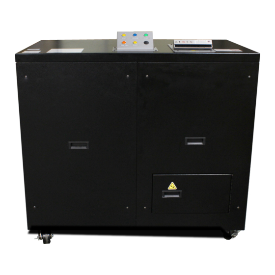
1. General Assembly Controls Drop Chute Hopper Top Cover Bed Knife Adjustment Screws Drawer Handle E-Stop Collection Bin Access Door Stage 2 Cutting Collection Bin Chamber Front of Cabinet 6 Pin Amphenol Connect E-Stop & Hour Filter Access Panel CE Serial Number Tag Meter IEC60320 Connector... - Page 6 Filter Stage 1 Chamber Power Cord Stage 2 Chamber Electrical Panel Rear w/ Cover Removed Contactors Overloads Fuses Electrical Panel 508.366.1488 | www.semshred.com...
-
Page 7: Unpacking Instructions
Remove the Model 2SSD from the pallet – lift truck Note: It is recommended to lift the Model 2SSD from the front with the forks 30” apart or using the fork pockets beneath the unit if ordered. Most of the weight will be on the right side of the Model 2SSD. -
Page 8: Power Supply/Installation Requirements
Intended Use: The SEM Model 2SSD is intended to shred and disintegrate solid state drives and electronic media. It can reduce media down to a particle size of 2x2mm depending on the size of the screen chosen. Larger screen mesh sizes are available for larger particles and faster throughput. -
Page 9: Startup And Operation
4. Startup and Operation Important: Most problems occur during the first hours of operation. These can be eliminated by careful review of the operating, maintenance and recommended service instructions. Warning: Use only intended materials in disintegrator or severe jamming may occur. See page 18. New Operators: It is recommended to give new operators approximately 2 hours for a break in period beginning with a slow feed rate to familiarize themselves with the device. -
Page 10: Startup Procedures
Disclaimer: If destroying lighter material in volume the BIN FULL light may not illuminate when the bin is filled. SEM recommends that the operator gauge how much material is run to avoid overflow and potential damage to the unit. - Page 11 6.) To release the jam, de-energize the unit (recommended that each site has a LOTO program in place), then unbolt and remove the top cover to gain access to the STAGE 1 chamber. SEM recommends using long pliers.
-
Page 12: Clearing A Jam/Accessing Stage 2 Cutting Chamber
4.5 Clearing a Jam/Accessing Stage 2 Cutting Chamber Jam Sensor: This device is now equipped with a jam prevention sensor. It is located on the right side of the stage 2 cutting chamber. This sensor detects the RPM of the rotor and processes that information to determine if there are any issues or jams with the machine. - Page 13 Accessing Stage 2 Cutting Chamber: 1. Disconnect all power to the unit using proper lockout-tag out procedures (LOTO). 2. Open front door. Be sure that foam blocks are removed before operating Figure 3 Remove the two painted side bolts holding the cutting chamber drawer in place (see figure 3). Note: Never operate the machine without the bolts in place.
- Page 14 5. Pull cutting chamber drawer all the way out (see figure 6). Figure 6 – Pull Handle a. Brush should clear off any debris on top of the hopper and remain partially on the hopper once the drawer has been fully pulled out. Figure 7 –...
- Page 15 Figure 8 b. Requires 7/16” socket wrench. c. Bolts to be removed. Figure 9 – Figure 10 Belt Side 508.366.1488 | www.semshred.com...
- Page 16 6. Clear the jam a. Ensure that the rotor can make the full 360° of rotation otherwise it is still jammed. b. In the event that the operator cannot clear out all the material from the cutting chamber, the screen may need to be removed (see page 22). Figure 11 7.
- Page 17 Figure 13 c. After aligning, tighten front two bolts, recheck alignment, and tighten the back two. 9. Close the drawer, making sure the brush has been removed. 10. Reinstall brush bolts, keeping the bolts loose and align brush with the front edge of the hopper, approximately ¼”...
-
Page 18: Shutdown Procedures
Model 2SSD. This will often involve opening the product Catastrophic damage to the before running it through the unit. -
Page 19: Maintenance
• Vacuum (see spare parts) Mask or respirator Warning: Shredded material can be sharp; SEM recommends wearing gloves. Stage 2 Cutting Chamber: See page 10 for instructions on accessing the stage 2 cutting chamber. 5.1 Daily Cleaning 1. Disconnect all power from the unit. -
Page 20: Lubrication
One grease fitting per bearing, see diagram. 5.3 Fan Cleanout The filter fan must be cleaned regularly to avoid excessive noise, dust buildup, and to ensure proper air filtration. SEM recommends cleaning every 500 drives. • Remove the back panel opposite the cutting chamber access door. -
Page 21: Filters
5.4 Filters About the Filters: This device utilizes a 99.7% efficient (based on a 0.3 micron particle), UL certified HEPA filter. This is coupled with a carbon pre-filter to capture as many air contaminants as possible. Frequency of Change: The following times are manufacturer recommended. Devices that see heavy use, quick feed rates, or smaller waste screens will require more frequent filter changes and cleaning. -
Page 22: Remove Screen
5.5 Remove Screen 1. Requires ½” deep socket 2. See page 10, skip steps 5 through 8. 3. The screen will be exposed under the platform. Remove six 5/16-18 nuts from the screen, using a 1/2” deep socket with extension and lower it carefully to not spill any remaining material. 4. -
Page 23: Belt Adjustment
8. Proper belt tension is determined by pinching both belts between the thumb and forefinger and causing a bow on the slack Fig. side. This should be approximately 7/32”. a. SEM recommends using a belt tensioning Bolts to loosen gauge. See step 12. -
Page 24: Changing Knives
25 hours of usage to avoid excess dust and potential jams or post every 500 devices. Note: SEM highly recommends that this work be completed by SEM trained technicians. Damage to equipment and harm to personnel may occur if work is not performed correctly. - Page 25 Spare Knives and Sharpening: To avoid downtime, it is best to have a spare set of sharp knives on hand at all times. SEM offers spare knives and sharpening services. Contact SEM Customer Service for details. Screen: It is recommended, but not required, to remove the screen from the chamber while changing the knives.
- Page 26 Remove front and rear deflectors. Requires 1/2” wrench. Bolts to Remove (Both Sides) Rear Deflector Front Deflector Figure 3 Figure 4 Remove bolts from rotor knives and remove knives. o CAUTION – Knives are sharp. o Requires 5/16” Allen drive socket bit. Remove bolts from bed knives.
- Page 27 Bed Knife Bed Knife Bed Knife Support Figure 6 – Bed Knives as seen from Bed Knife Support Drive Plate Install bed knife bolts with six 3/8”- 16 x 1 1/2" socket head cap screw and six 3/8” thick black washer through top of clamp –...
- Page 28 Torque rotor knives to 50-55ft./lbs. Requires torque wrench and 5/16” Allen drive socket bit Rotor Knife Bolt Figure 8 Set clearance between rotor and bed knives to .005” using adjustment screws and a feeler gauge, rotating the knives in reverse (clockwise) so “flat to flat” contact will not cut feeler gauge. o Requires 7/16”...
- Page 29 Re-sharpening: Knives can be re-sharpened 2-3 times provided they are not significantly damaged or worn. Knives must be sharpened as a complete set (two bed knives, three rotor knives). Contact SEM Customer Service for details or for replacement knives.
-
Page 30: Current Relay Adjustment
5.7 Current Relay Adjustment Tools and PPE Required: • 5/32” Allen wrench • Small Philips head screwdriver About the Current Relay: This device is designed to automatically reverse if it jams while shredding. The electrical current relay controls this feature and is preset by the factory prior to shipping. However, power variations can cause the device to jam and not reverse. -
Page 31: Plastic Shield Adjustment
5.8 Plastic Shield Adjustment Tools and PPE Required: • 5/32” Allen wrench Adjusting: • Located on either side of the hopper are plastic shields that may require periodic adjustment. • Loosen the three screws holding the black metal bar in place just enough for the shield to move. Plastic Shield •... -
Page 32: Available Spare Parts
6. Available Spare Parts ITEM DESCRIPTION PART/DWG# Spare Set of Knives (3 Rotor/2 Bed) designed for Model 2SSD 3912SSDK/3SP Spare Sizing Screen designed specifically for Model 2 SSD (1/8) SSD-2SCREEN184P Spare Waste Collection Bin for Model 2 SSD WCB-2SSD Carbon Pre-Filter for Model 2 SSD (3-pack)
Need help?
Do you have a question about the 2SSD and is the answer not in the manual?
Questions and answers