Table of Contents
Advertisement
Quick Links
BROBO GROUP (AUST) PTY. LTD.
8 Fowler Rd, Dandenong, 3175
Victoria, AUSTRALIA.
✆
61 3 9794 8751
Fax: 61 3 9794 8792
PRODUCT AND MA INTENANCE MANUAL
BDF32-1 & BDF45-1
GEARED HEAD DRILL
YOUR BROBO DISTRIBUTOR IS:
Precision Drilling Machines Tapping Machines Multi-Head Drills Tool Grinders
Tool Post Grinders Machine Vices Special Production Equipment
Accessories Riveting Machines Pedestal Grinders Metal
✉
W:
cutting Saws Linishers
MANUFACTURED IN CHINA
A.C.N.
098 264 316
A.B.N. 42 098 264 316
:
info@brobo.com.au
www.brobo.com.au
Quality
Endorsed
Company
ISO 9001 Lic. 10292
SAI GLOBAL
Advertisement
Table of Contents

Subscribe to Our Youtube Channel
Related Manuals for Brobo BDF32-1


Summary of Contents for Brobo BDF32-1
- Page 1 A.C.N. 098 264 316 A.B.N. 42 098 264 316 Quality Endorsed BROBO GROUP (AUST) PTY. LTD. Company ISO 9001 Lic. 10292 8 Fowler Rd, Dandenong, 3175 SAI GLOBAL Victoria, AUSTRALIA. ✆ ✉ 61 3 9794 8751 info@brobo.com.au Fax: 61 3 9794 8792 www.brobo.com.au...
-
Page 2: Table Of Contents
PRODUCT MANUAL FOR BDF32-1 & BDF45-1 GEARED HEAD DRILL CONTENTS SAFETY 1. OUTLINE DRAWING 2. TECHNICAL SPECIFICATION 3. MAIN APPLICATIONS AND FEATURES 4. TRANSMISSION SYSTEM 5. ELECTRICAL SYSTEM 7, 8 6. LUBRICATION 7. LIFTING & INSTALLATION 10-11 8. MAIN FUNCTIONS & OPERATION OF THE MACHINE 12-13 9. - Page 3 Preparation for Operation The following procedure is recommended for the correct drilling using the Brobo Group Drill WARNING – SAFETY GEAR Protective clothing, safety glasses and gloves should always be worn while loading parts, operating the machine, or undertaking any maintenance work on the machine.
- Page 4 Never move the drill while the machine is operating. Always keep the workplace are as clean as possible. Remove equipment, tools or any other objects from the drilling zone. Support the workpiece to prevent it falling or jamming during the drilling cycle. Brobo Group brobo.com.au...
-
Page 5: Safety
This could damage the drill, the specimen or be a cause for potential injury to the operator. Always turn off the machine before carrying out any repair work. Consult the Brobo Group Engineering Department in the country in which the machine was initially purchased. Machine Safety Devices This product &... -
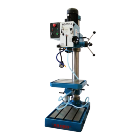
Page 6: Outline Drawing
1. Outline Drawing BDF 32-1 Figure 1... -
Page 7: Technical Specification
2. Technical Specifications MODEL BDF32-1 BDF45-1 Max. drilling capacity 32mm 45mm Taper of spindle hole Morse No.3 Morse No.4 Max. travel of spindle 130mm Distance between the centre of spindle and 283mm the surface of the vertical column Maximum distance between the spindle... -
Page 8: Main Applications And Features
3. Main Applications and Features Applications include drilling, spot facing, chamfering, reaming, tapping and boring. The headstock and worktable are easily adjusted, the headstock and worktable can be moved up and down and be rotated 360° around the vertical column. The headstock and worktable can also be leaned ±90°... - Page 9 Figure 2 (Drawing of Transmission System)
-
Page 10: Electrical System
5. Electrical system POWER SUPPLY AUSTRALIA: 50 Hz 415 VAC 3 Ø USA: 60 Hz 220/460 VAC 3 Ø Figure 3 (layout) -
Page 12: Lubrication
6. Lubrication Top up lubrication oil No. 30 to the headstock every 6 months, the lubrication oil should be added once a week (ball valves), reference figure 5 for the location of lubrication. ONCE EVERY 6 MONTHS BDF 32-1 ONCE A WEEK Figure 5 (Diagram of Lubrication) -
Page 13: Lifting & Installation
7. Lifting and Installation All locking handles must be locked before lifting (Lifting point shown in figure 6). When installing the machine, bury the foot-screw in a cement foundation according to the position of base holes, after the cement has condensed completely, place the machine on the cement foundation and secure to footing screws. - Page 14 Figure 7 (Installation of Foundation)
-
Page 15: Main Functions & Operation Of The Machine
8. Main Functions and Operation of the Machine BDF 32-1 Name Name Feed handle of spindle Depth setting nut Speed change handle Lock handle of working-table Speed change handle Lock handle of headstock Micro feed handle Tool retracting handle Up and down handle of supporting block Control panel of electric Lock handle of supporting block Block of Scale orientation... - Page 16 MAIN SPINDLE CONTROL Main Spindle Control has “forward, reverse and stop” positions. ADJUSTING HEADSTOCK By loosening the lock handle (11) & turning handle (7), the headstock can be moved up and down. Loosening the lock nuts on the headstock allows the headstock to be leaned ±90º. Make sure to lock the handle (11) and all lock nuts before operating the drill.
-
Page 17: Assembly Drawings & Spare Parts List
9. Assembly Drawings & Spare Parts List... - Page 19 PART NO. Z5040-01-001 Base Z5040-01-009 GB823-85 Screw M5×10 GB/T 301-199 Bearing 51124 Z5040-01-003 Turning ring B GB70-85 Screw M8×30 Z5040-01-005 Immobility ring A GB/T 301-199 Bearing 51124 Z5040-01-006 Turning ring A Z5040-01-008 Immobility ring B GB70-85 Screw M8×20 GB825-88 Eye screw D96-5 Hose connector Z5040-01-007...
- Page 20 Z5040-02-014 Cover Z5040-02-004 Locking block A Z5040-02-001 Supporting black Z5040-02-004 Locking block B Z5040-02-005 Locking shaft Z5040-02-006 Shaft GB4141.12-84 Handle GB/T95-85 Washer 16 GB/T41-86 Nut M16 GB/T818-85 Screw M5×10 ZX32G-02-021 Angle meter GB4141.12-84 Handle Z5040-02-008 Handle shaft Z5040-02-010 Pin shaft Z5040-02-011 Locking handle base Z5040-02-007...
- Page 22 PART NO. DESCRIPTION JB/T7273.2 Hand wheel 12×100 JB/T7270.4 Handle M8×10 GB/T77-85 Screw M8×10 ZX32-05-002 Dial seat ZX32-05-004 Dial ring GB/T70-85 Screw M5×15 ZX32G-04-009 Cover ZX32G-04-007 Bearing spacer ZX32G-04-006 Bearing 6202 JB/T7271.1-94 Worm shaft JB/T7271.6-94 Lock bolt with knob ZX32G-04-004 Knob ZX32G-04-005 Knob rod GB/T1096...
- Page 23 Z5040-02-012 Retain ring (external) 10 GB/T276-94 To raise and lower body GB/T893.2-86 Locking shaft GB/T9877.1 Bearing 6007 ZX32G-02-045 Inner ring B62 ZX32G-02-011 Oil seal GB/T118-86 Oil filler cover ZX32G-04-008 Head body cover GB/T276-94 Taper pin 10×50 GB/T1096 Key 6×35 Motor GB/T95-85 Washer 10 GB/T93-85...
- Page 24 GB/T1096 Key 5×25 ZX32G-02-023 Shaft ZX32G-02-024 Gear GB/T1096 Key 6×12 ZX32G-02-017 Shaft GB/T1096 Key 5×60 GB/T73-85 Screw M5×8 ZX32G-02-020 Gear ZX32G-02-019 Gear GB/T308-84 Steel ball 8 GB/T2089-84 Spring ZX32G-02-018 Gear GB/T894.1-94 Retain ring (external) 18 GB/T276-94 Bearing 6202 GB/T893.2 Retainer ring (internal) 35 GB/T893.2 Retainer ring (internal) 35 GB/T276-94...
- Page 25 GB/T894.2 Retain ring (external) 35 GB/T276-94 Bearing 6007 ZX32G-02-012 Spacer GB/T893.2-86 Retainer ring (internal) 62 GB/T276-94 Bearing 6007 ZX32G-02-010 Gear ZX32G-02-009 Spindle sleeve gear GB/T1096 Key 6×18 ZX32G-02-041 Screw knob ZX32G-02-042 Washer ZX32G-02-043 Spring cover ZX32G-02-047 Spring ZX32G-02-040 Spring base GB/T70-85 Screw M5×10 ZX32G-02-039...
- Page 26 ZX32G-02-026 Pin shaft ZX32G-02-027 Lever ZX32G-02-028A Lever shaft (long) B4141.12-84 Handle Z5040-02-008 Handle shaft Z5040-02-010 Pin shaft Z5040-02-011 Locking handle base Z5040-02-007 Locking handle base Z5040-02-009 Lever GB/T79-85 Round head fasten screw Z5040-02-013 Washer 16 GB6172-86 Thin nut M16 GB923-88 Nut M16 GB1235-76 O-ring 14*3.1...
- Page 28 PART NO. DESCRIPTION ZX40G-03-001 Spindle GB/T858-88 Stop washer 30 GB/T810-86 Nut M30×1.5 GB/T5780-86 Bolt M6×50 ZX40G-03-003 Graduate rod base GB/T41-86 Nut M6 ZX40G-03-002 Anti-dust ring GB/T297-94 Bearing 30208/P6 ZX40G-03-005 Rack sleeve ZX32G-03-004 Rubber flange GB/T297-94 Bearing 30206/P6 GB/T879-86 Spring pin φ3×18 ZX32G-03-010 Handle ZX32G-03-009...
-
Page 29: Brobo Group Warranty
This warranty is given by Brobo Group Pty Ltd, ABN: 42 098 264 316 Address: 8 Fowler Rd, Dandenong, VIC 3175 ✆...
Need help?
Do you have a question about the BDF32-1 and is the answer not in the manual?
Questions and answers