Sign In
Upload
Download
Table of Contents
Contents
Add to my manuals
Delete from my manuals
Share
URL of this page:
HTML Link:
Bookmark this page
Add
Manual will be automatically added to "My Manuals"
Print this page
×
Bookmark added
×
Added to my manuals
Manuals
Brands
Trocen Manuals
Security Sensors
AWC78 Series
User manual
Trocen AWC78 Series User Manual
Laser motion controller
Hide thumbs
1
2
3
4
Table Of Contents
5
6
7
8
9
10
11
12
13
14
15
16
17
18
19
20
21
22
23
24
25
26
27
28
29
30
31
32
33
34
35
36
37
38
39
40
41
42
43
44
45
46
47
48
49
50
51
52
53
54
55
56
57
58
59
60
61
62
63
64
65
66
67
68
69
70
71
72
73
74
75
76
77
78
79
80
81
82
83
84
85
86
87
88
89
90
91
92
93
94
95
96
97
98
99
100
101
102
103
104
105
106
107
108
109
110
111
112
page
of
112
Go
/
112
Contents
Table of Contents
Bookmarks
Table of Contents
Table of Contents
1 Product Description
Features
AWC78XX Series Comparison
Term/Abbreviation
AWC7813 Accessories Composition
AWC7813 All Accessories and Connection Diagram
List of Accessories
Appearance and Size of Panel
Appearance and Size of Wiring Board
2 Hardware Interface Introduction
Control System Electrical Wiring Diagram
Wiring Board Unit Port Description and Wiring Diagram
Power Port
Universal Input Port
Universal Output Port
Laser Power Control Port
Motor Driver Control Port
Limit Signal Input Port
Mainboard Interface Description
U Disk Interface
USB Interface
Ethernet Interface
Panel and Terminal Board Interface
3 Human Machine Interface Introduction
Main Interface Preview
Function Key Area
Reset
File
Menu
More
Laser
Box
Origin
Stop
Start
Pause
Interface Switching
Direction Key Area
X,Y Axis Movement Keys
Fast and Slow Movement Switch Key
Z Axis Movement Button
Processing Time Display Area
Status Display Area
Lock Screen, Unlock Screen
Coordinate Display Area
The Coordinate System with the Machine Zero in the Upper Right
Corner
The Coordinate System with the Machine Zero in the Lower Right
Current Processing File Name Display Area
The Properties of the Processing File
Layer Parameters of Processing Files
Count Display Area
Speed Display Area
Quickly Modify the Key Move Speed in Standby Mode
Modify the Speed of the File Being Processed
Power Display Area
Modify Laser Power
Modify the Power of the File Being Processed
File Operations
U Disk Transfer Files and Mainboard Upgrade
Use U Disk to Transfer Files to Mainboard
Upgrade the Mainboard
Origin Manage
Set Origin Coordinates
Move the Laser Head to the Set Origin
Motion Parameters Settings
Description of each Parameter
Space Speed
Cut Jerk
Space Jerk
Min Acc
Engrave Acc
Start Speed
Speed Factor
Example Analysis
Wavy Lines Appear When Cutting Arcs
Wavy Lines Appear at the Beginning and Corners of the Cutting52
Common Parameters Settings
Work Mode
Go Origin after Reset
Origin Mode
Go Back Position
Count Mode
Common Parameters
Autofocus Distance(MM)
Keymove'speed(MM/S)
Runbox'speed(MM/S)
Cutbox'speed(MM/S)
Blow Open Delay(S)
Blow Close Delay(S)
Axis Speed Parameters
Z Work Speed(MM/S)
XY Home Speed(MM/S)
Z Home Speed(MM/S)
Rotate Engraving & Cutting
Manufacturer Parameters Settings
Axis Parameters(Take X Axis as an Example)
Distance Per Pulse(Um)
Valid Pulse Edge
Datum Direction
Key Direction
Limit-Switch Valid Level
Range(MM)
Start Speed
Max Acc
Max Speed
Zero Offset
Laser Parameters
Laser Mode
TTL Valid Level
PWM Frequency(Hz)
Max Power(%)
RF Min Power(%)
Laser 1 Water Protect
IO Parameters
Foot Switch
Open Protection
Input Valid Level
Autoreset Settings
Hardlimit Settings
Function Configuration
Z-Axis for Autofocus
Y&Z Double-Driver Control
Network Settings
Language
System Version
Input Test
Output Test
Cut Box
Axis Reset
Key Moving
Z Autofocus, X&Y to Origin and Continue to Previous Work
Run Z Autofocus Function
Set X&Y to Origin
Continue to Previous Work
4 Frequently Asked Questions
What Kind of U Disk Can the System Read
Why Does the Prompt "Engrave Beyond Border Limit!" Appear
Why Does the Prompt "Beyond Border Limit! Continue?" Appear
Why Does the Prompt " Beyond Border Limit!" Appear
Why Does the Prompt "Trigger Limit!" Appear
Why Does the Prompt " no File!" Appear
Why Does the Prompt "To Select the File!" Appear
Why Does the Prompt "Continue to Work?" Appear
Rotary Engraving Function
Why Does the Prompt "Water Protect!" Appear
Why Does the Prompt "Opened Protected!" Appear
5 Operation Process Description
Machine Installation and Debugging Process
Basic Steps of Using the Laser Machine to Cut Graphs
Advertisement
Quick Links
1
Awc7813 All Accessories and Connection Diagram
Download this manual
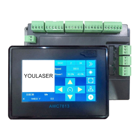
AWC7813 motion controller
User manual
Laser motion controller series
RV1.3
2020.08
WWW.SZTROCEN.COM
1
www.sztrocen.com/www.awc608.com
©
2016 Trocen All Rights Reserved
Table of
Contents
Previous
Page
Next
Page
1
2
3
4
5
Advertisement
Table of Contents
Need help?
Do you have a question about the AWC78 Series and is the answer not in the manual?
Ask a question
Questions and answers
Related Manuals for Trocen AWC78 Series
Controller Trocen AWC7824 User Manual
Laser motion controller (148 pages)
Security Sensors Trocen AWC7813 User Manual
Laser motion controller (112 pages)
Security Sensors Trocen AWC708S User Manual
Laser motion control (97 pages)
Security Sensors Trocen TC-6832 Operation Manual
(48 pages)
This manual is also suitable for:
Awc7813
Awc7824
Awc7846
Table of Contents
Save PDF
Print
Rename the bookmark
Delete bookmark?
Delete from my manuals?
Login
Sign In
OR
Sign in with Facebook
Sign in with Google
Upload manual
Upload from disk
Upload from URL


Need help?
Do you have a question about the AWC78 Series and is the answer not in the manual?
Questions and answers