Makita BO6040 Technical Information
Hide thumbs
Also See for BO6040:
- Instruction manual (29 pages) ,
- Parts breakdown (3 pages) ,
- Instruction manual (17 pages)
Advertisement
Quick Links
T
ECHNICAL INFORMATION
Models No.
Description
C
ONCEPTION AND MAIN APPLICATIONS
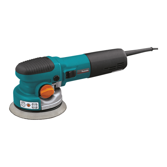
This models is versatile random orbit sander for
professional use.
Due to the two mode selection,
"Forcible rotation mode" / "Free-rotation mode",
rough sanding, fine finishing and polishing can be done
only with this machine.
S
pecification
Voltage (V)
110
120
220
230
240
Orbits per min. : (min
Oscillation rate per min.: spm = min
Rpm.of pad with Forcible-Rotation : rpm = min
Orbit diameter : mm (")
Pad diameter : mm (")
Cord length : m ( ft )
Net weight :Kg (lbs )
S
tandard equipment
* Pad 150 (soft ) ........................................................... 1pc. (factory-attached to the machine)
* Abrasive disc 150-120 (Hook and loop type) ........... 1 pc.
* Hex wrench 6 ........................................................... 1 pc.
* Joint ........................................................................... 1 pc. ( only for European market)
< Note > The standard equipment for the tool shown may differ from country to country.
O
ptional accessories
* Pad 150 ( hard)
* - ditto - ( soft)
* - ditto - ( super soft)
* Abrasive disc 150 - 40, 60, 80, 120, 180, 240, 400
* Sanding cloth 150 - 100, 200, 800
BO6040
150 mm Random Orbit Sander
Cycle (Hz)
Current (A)
7.2
50 / 60
6.6
50 / 60
3.6
50 / 60
3.4
50 / 60
3.3
50 / 60
= spm)
-1
-1
W
Continuous Rating (W)
Input
750
750
750
750
750
1,600 - 5,800
3,200 - 11,600
180 - 670
-1
5.5 ( 7/32)
150 ( 6 )
2.5 ( 8.2 )
2.7 ( 5.9 )
* Sponge pad 150 ( hook and loop type)
* Felt pad 150 ( hook and loop type )
* Wool pad 150 ( hook and loop type )
* Side grip
PRODUCT
L
H
Dimensions : mm ( " )
Width ( W )
150 (5-7/8)
Height ( H )
132 (5-3/16)
Length ( L )
316 (12-1/2)
Max. Output(W)
Output
390
850
390
850
390
850
390
850
390
850
P 1 / 10
Advertisement

Related Manuals for Makita BO6040


Summary of Contents for Makita BO6040
- Page 1 ECHNICAL INFORMATION PRODUCT P 1 / 10 Models No. BO6040 Description 150 mm Random Orbit Sander ONCEPTION AND MAIN APPLICATIONS This models is versatile random orbit sander for professional use. Due to the two mode selection, "Forcible rotation mode" / "Free-rotation mode", rough sanding, fine finishing and polishing can be done only with this machine.
- Page 2 P 2 / 10 epair < 1 > Replacing armature and spiral bevel gear 9 1) Take off tapping screw 4x18 and detach rear cover from motor housing. And detach carbon brush as illustrated in Fig1. Carbon brush Tapping screw 4x18 Rear cover Motor housing Fig.
- Page 3 P 3 / 10 epair < 2 > Replacing ball bearing 6201LLB installed in skirt Head cover (1) Unscrew flat head screw M8x11 and detach head cover from gear housing. See Fig.5. (2) Unscrew pan head screw M4x12 and detach skirt from gear housing. See Fig.5. Flat head screw M8x11 Pan head...
- Page 4 P 4 / 10 epair (4-A) If "spur gear 26 complete" is loosened first, Remove "spur gear 26 complete". And loosen hex nut M10 with box wrench 17, gripping upper balance weight with monkey wrench 250mm. See Fig. 8. Box wrench 17 Monkey wrench 250mm Upper balance Spiral bevel gear 42...
- Page 5 P 5 / 10 epair (7) Remove internal gear 29, ball bearing 6811LLB and stop ring WR-55 by striking skirt on the work-table covered with soft sheet as illustrated in Fig.11. And then, remove lower balance weight. Skirt Stop ring WR-55 Lower balance Strike on the work-table weight...
- Page 6 P 6 / 10 epair (9-2) Assemble spiral bevel gear 42,upper balance weight and flat washer 10. And then, tighten hex nut M10 provisionally. Assemble internal gear 29 after installing lower balance weight. Flat washer 10 Hex nut M10 Upper balance weight Spiral bevel gear42...
- Page 7 P 7 / 10 epair < 3 > Replacing ball bearing 6001DDW installed in "spur gear 26 complete" See Fig. 16. Sleeve 1) In order to replace ball bearing 6001DDW, the removed spindle is needed as a repairing tool. Ball bearing 6001DDW Screw spindle into sleeve installed in "spur gear 26 complete"...
- Page 8 P 8 / 10 epair 4) Assembling ball bearing 6001DDW installed in "spur gear 26 complete" Assemble sleeve to new ball bearings 6001DDW by pressing it, and assemble retaining ring S-12 to sleeve. And then, press them into spur gear 26. See Fig. 20. Sleeve Ball bearing 6001DD Retaining ring S-12...
-
Page 9: Circuit Diagram
P 9 / 10 ircuit diagram Model BO6040 Brush holder ( switch block side ) White Black White or blue Switch block Field Power supply cord Orange Speed Controller Control Dial White Brush holder ( controller side ) < Note >... - Page 10 P 10 / 10 iring diagram Model BO6040 Fix lead wire of controller with lead holder between pin A and pin B. Inflect the lead wire at the terminal Put the lead wires of controller in the lead holder in right angle. See Fig 24A.
Need help?
Do you have a question about the BO6040 and is the answer not in the manual?
Questions and answers