Table of Contents
Advertisement
Quick Links
www.DanaherMotion.com
®
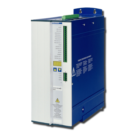
SERVOSTAR
S600
Electronic Gearing and
Software User Interface
®
This Product Note describes how gearing works on the SERVOSTAR
S600. It begins with a
general discussion of gearing and continues with details on hardware and software set up. This
document only describes the software setup for gearing using the Software User Interface for the
SERVOSTAR S600.
How Electronic Gearing Works
Electronic gearing provides a position command to a drive that depends on the motion of another
device. That device is typically an encoder (or its equivalent) connected to a motor. However, it
can also be a hand-driven encoder used to accept input from an operator or an output from a stepper
motor controller. This is different from internal profile generation where position commands are
calculated inside the drive based on motion parameters, such as distance, acceleration, and velocity.
The external encoder signal provides an input to the gearing software. In many applications, the
motor follows the input, step for step where one revolution of the input device should create one
revolution in the electronically-geared motor. This is called one-to-one gearing.
Other times, it is necessary to have a non-unity scale factor. The gear ratio may be a non-integer,
such as 1:3. It is important that the gearing software not introduce round-off errors when the gear
ratio is non-integer because over long periods of time, the round-off error accumulates and causes
the electronically-geared motor to drift with respect to the input. The SERVOSTAR S600 supports
non-integer gearing ratios while remaining free of round-off errors.
Gearing Applications
There are several ways to use electronic gearing in applications. They vary depending on the source
of the input signal and how the gear ratio is set. However, they all share the structure where the
electronically-geared drive controls the motor to follow the input.
Following a Non-Driven Encoder
Some gearing applications require that a servomotor follow a non-servo-driven encoder. The
encoder may be on an idle roller of a conveyor belt or in a line-driven induction motor. The
encoder is connected to an axis that is not under the direct control of another drive.
Advertisement
Table of Contents

Related Manuals for Danaher Motion SERVOSTAR S600


Summary of Contents for Danaher Motion SERVOSTAR S600
- Page 1 1:3. It is important that the gearing software not introduce round-off errors when the gear ratio is non-integer because over long periods of time, the round-off error accumulates and causes the electronically-geared motor to drift with respect to the input. The SERVOSTAR S600 supports non-integer gearing ratios while remaining free of round-off errors.
- Page 2 The SERVOSTAR S600 encoder emulation circuit produces output signals equivalent to an encoder from any feedback device that is used as the main feedback device. This allows any SERVOSTAR S600 to serve as the master for any other electronically-geared SERVOSTAR S600.
- Page 3 The material is stretched across two rolls. The faster the outtake roll spins, the greater the tension held across the web. The SERVOSTAR S600 provides several ways to adjust this gear ratio. Figure 5 shows a control scheme where one analog input commands speed of the master axis and the slave axis follows that command according to the gear ratio.
-
Page 4: Following Error
Determine the Encoder Type Encoder Voltage The first step to selecting the encoder is determining the voltages. The SERVOSTAR S600 accepts signals with three voltage levels: • 0 to 5 VDC via Connector X5 •... - Page 5 Figure 6: Connector Locations and Pin-outs Document Number: P-SS-004-09 Rev 5 Old Numbers (AS6007H, A-SS-004-20208) Revised 11/20/2003 www.DanaherMotion.com Page 5...
- Page 6 Most optical encoders provide 0 to 5 VDC signals. The encoder emulation output from another (master) SERVOSTAR S600 are also 0 to 5 VDC signals and should be brought into Connector X5. A SERVOSTAR S600 cannot simultaneously take 0 to 5 VDC connections into Connector X5 and provide encoder emulation outputs because both signals share the same pins on Connector X5.
- Page 7 Figure 8: Step/Direction Encoder Format Some encoders provide a single channel output. If you are using such an encoder, use the step/direction format. Connect the output channel to the step input and tie the direction channel either high or low, as is appropriate for the application requirements. •...
- Page 8 Sometimes is it desirable to connect electronically-geared drives in a chain. In this configuration, a single SERVOSTAR S600 is master to one axis and slave to another. This configuration is supported in the SERVOSTAR S600 if the drives use sine encoders. Because a single SERVOSTAR S600 cannot have encoder emulation and 0 to 5 VDC encoder input operating simultaneously, it is not possible to chain drives using the 0 to 5 VDC inputs.
-
Page 9: Software Setup
SERVOSTAR S600. The Software User Interface provides a user-friendly graphical interface and terminal for the setup, monitoring, and troubleshooting of the SERVOSTAR S600. When setup is complete, save your settings to the EEPROM. Otherwise, all settings are lost at power down or during a “COLDSTART.”... - Page 10 Selecting the Gearing Mode (GEARMODE) Select the gearing mode (GEARMODE) based on the hardware used for the encoder input. Currently, there are six choices: GEARMODE Encoder Input Voltage Levels and Format Digital quadrature format with 0 to 24 VDC Inputs (Connector X3). Step/direction format with 0 to 24 VDC Inputs (Connector X3).
- Page 11 To access the Gearing dialog box, click Position in the Amplifier dialog box (Figure 11). Click Gearing, located near the bottom-right of the displayed Position dialog box (Figure 12). From the Gearing dialog box, select the appropriate value of GEARMODE from the Gearing Mode drop- down box at the top of the window.
- Page 12 Selecting Velocity or Position Control (EXTPOS) Select whether you want the encoder input to represent a position command or a velocity command. For most applications, the setting is a position command. In some applications, the encoder input may represent a velocity command. The most common example of this is when a multi-pulse generator (MPG) is used by a machine operator to command speed.
- Page 13 Whether you use the Gearing dialog box or the terminal window, you can set the encoder resolution only to one of eight values: 256, 512, 1024, 2048, 4096, 8192, 16384, 32768, and 65536. If your encoder has non-binary resolution (for example, 1000 lines/revolution), select the resolution closest to your encoder.
-
Page 14: Realtime Adjustments
Realtime Adjustments You can adjust the gear ratio of the SERVOSTAR S600 in realtime. Use caution when changing the gear ratio on-the-fly as this could produce unexpected results. Realtime gear ratio variation is accomplished by modifying the constants GEARI or GEARO while the machine is in operation. - Page 15 Select the Analog Configuration (ANCNFG = 6) To use analog gearing, set the analog configuration to 6. To do this, click Analog I/O on the Amplifier dialog box (Figure 11). From the displayed Analog I/O dialog box (Figure 16), select 6. Analog Gearing from the Setp.
- Page 16 Synchronization (Simple PLL) The SERVOSTAR S600 supports synchronization between drives. This function acts like a phase- locked loop (PLL) that is sampled every 250 microseconds. The function relies on any one of the digital inputs to indicate the command needs to be adjusted by a fixed amount.
- Page 17 The SERVOSTAR S600 avoids rollover problems by using the encoder counts on a cycle-by-cycle basis. The only limitation is that the number of counts over a 250 µs period must be less than 8192.
-
Page 18: Troubleshooting
Troubleshooting If gearing is not working properly, the problem could be in one of two places: 1) getting the master signal into the drive and 2) calculating the geared command. Most problems are getting the master signal into the drive. The internal variable DF3MASTER allows you to monitor the gearing master signal.
Need help?
Do you have a question about the SERVOSTAR S600 and is the answer not in the manual?
Questions and answers