Table of Contents

Related Manuals for Jung 20320 1S IPS R


Summary of Contents for Jung 20320 1S IPS R
- Page 1 Product documentation Power supply ALBRECHT JUNG GMBH & CO. KG Volmestraße 1 with IP interface 58579 Schalksmühle GERMANY Ref.-no.: 20320 1S IPS R Tel. +49 2355 806-0 Fax +49 2355 806-204 kundencenter@jung.de www.jung.de 04/2020...
-
Page 2: Table Of Contents
6.4 Additional functions ....................6.4.1 General settings ........................... 6.4.2 Logic functions ..........................6.5 Object table ........................ 7 Advanced configuration ................31 7.1 Configuration tool ...................... 7.1.1 Device connection ........................7.1.2 Device configuration ........................7.2 Telnet interface ......................20320 1S IPS R Page 2 of 49... - Page 3 9.2.1 Deactivating secure commissioning ..................... 9.2.2 Downloading application program ....................9.3 Performing firmware update ..................10 FAQ ........................46 11 Terms .......................47 12 Technical data ....................48 13 Warranty ......................48 14 Open Source Software ...................49 14.1 LWIP ..........................20320 1S IPS R Page 3 of 49...
-
Page 4: Safety Instructions And Device Components
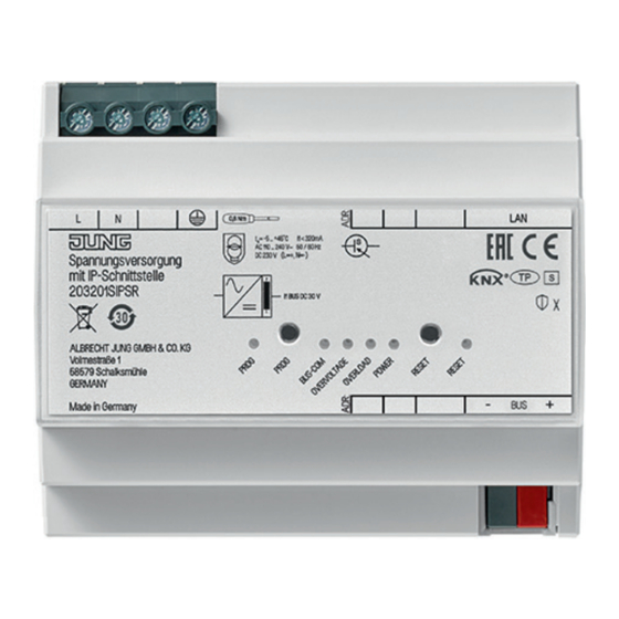
KNX connection PROG LED 11 POWER LED RESET LED BUS-COM LED Function 2.1 System information The device can be updated. Firmware can be easily updated. The device is KNX Data Secure capable. KNX Data Secure offers protection against manipulation in building automation and can be configured in the ETS project. Detailed specialist knowledge is required. A device certificate, which is attached to the device, is required for safe commissioning. During mounting, the certificate must be removed from the device and stored securely. Planning, installation and commissioning of the device are carried out with the aid of the ETS, version 5.7 and above. 20320 1S IPS R Page 4 of 49... -
Page 5: Intended Use
- Support of KNX Data Secure from ETS version 5.7 upwards - Support of KNX IP Secure from ETS version 5.7 upwards - LED display for KNX communication, Ethernet communication and programming mode - Configuration via ETS - SNTP server - Max. 8 connections to IP terminal devices, e.g. for simultaneous visualisation and configuration - Electrical isolation between KNX and IP network 20320 1S IPS R Page 5 of 49... -
Page 6: Information For Electrically Skilled Persons
- Power supply via a suitable circuit breaker • Connect protective conductor and mains voltage. • Connect LAN and KNX. i The bus load must not exceed the output current. i Do not connect any other products to the bus output. The bus communication could be affected by this. 20320 1S IPS R Page 6 of 49... -
Page 7: Commissioning
4.2 Boot procedure The automatic boot procedure starts after switching on. The six LEDs flash on the front of the device as a running light during the boot procedure. The duration of the boot procedure is prolonged if the IP address is assigned to the device via DHCP. DHCP is specified by the factory settings. The green POWER LED flashes during the assignment of the IP address. At the end of the booting procedure, the green POWER LED lights up. 20320 1S IPS R Page 7 of 49... -
Page 8: Operation
5.2 Programming mode Program interface: • Press PROG button. PROG LED lights up red. Program product application: • Press the PROG button again. PROG LED flashes red. Terminate programming mode: • Press the PROG button again. 20320 1S IPS R Page 8 of 49... -
Page 9: Diagnostic Messages
Power supply on the device bus is interrupted and the device bus is short-circuited. Power is switched on again. 5.5 Master reset • Ensure that the device is switched off (disconnect bus voltage and power supply). • Press PROG button, hold it and connect device. Device switches on. • Hold PROG button until PROG LED flashes slowly (approx. 1 Hz). • Release PROG button. • Press PROG button again and hold it until PROG LED flashes fast (approx. 4 Hz). The master reset starts. • Release PROG button. 20320 1S IPS R Page 9 of 49... -
Page 10: Configuration
6.2 Device properties 6.2.1 General Fig. 5: Properties of the device Function Description Name Any name can be assigned, max. 50 characters. Secure Commissioning If activated, the encryption is active for commissioning: all parameters are then transmitted in encrypted form, although e.g. Tunnel connections are still unencrypted. Secure Tunneling If activated, the tunnel connections can only be established via KNX Secure Tunneling. 20320 1S IPS R Page 10 of 49... -
Page 11: Ip Properties
ETS. 6.2.3 KNX IP Secure For an error-free operation of the devices in secure mode the ETS 5.7.4 or higher is required. Requirements: - Safe commissioning activated - FDSK entered/scanned or device certificate added Configuration of KNX IP Secure: • Activate secure tunnelling. • Define a password for each tunnel (max. 8 tunnels). • Define a password for commissioning and authentication code. i Document all passwords and store them securely. 20320 1S IPS R Page 11 of 49... -
Page 12: Additional Functions
Configuration 6.2.4 Additional functions Fig. 7: Additional functions of the device Function Description Name Any name can be assigned, max. 50 characters. 20320 1S IPS R Page 12 of 49... -
Page 13: Knx Data Secure
A combined operation of secure and conventional communication is possible at a sensor or actuator via different communication objects. But the communication via Secure and Unsecure with one and the same group address and therefore the same object is not possible. 20320 1S IPS R Page 13 of 49... -
Page 14: Device-Specific Parameters
Advanced functions to ensure a maximum of flexibility. 6.3.2 Advanced settings Fig. 9: Advanced settings of the device Function Options Description Max. number of telegrams 5 .. 50 See parameter description to KNX TP 20320 1S IPS R Page 14 of 49... - Page 15 1.0 ... 8.0 sec Setting of timeout for tunnel connection over Preferred IP for tunnel X off/on Tunnel X should preferably be used for communication with the parametrized IP address. End device IP (IP-V4 address) IP address of end device 20320 1S IPS R Page 15 of 49...
-
Page 16: Additional Functions
In this area the presence monitoring (with key card holder or with presence detector) can be configured and the triggers for Welcome/Goodbye scenes can be configured. Use Welcome/Goodbye active/inactive When active, the area for Welcome/Goodbye scene? scenes will be unlocked. In this area the triggers for Welcome/Goodbye scenes can be configured and the Welcome/Goodbye scenes can be configured. 20320 1S IPS R Page 16 of 49... - Page 17 Description Type of presence monitoring With key card holder/ When active, the area for presence monitoring will be unlocked. In this With presence detector area the presence monitoring (with key card holder or with presence detector) can be configured and the triggers for Welcome/Goodbye scenes can be configured. 20320 1S IPS R Page 17 of 49...
- Page 18 Activation trigger 2 (e.g. key Switch to On/ The activation of trigger 2 can be card holder) by Switch to Off/ selected. By selecting “Switch-over“ Switch-over the trigger is activated by switching to On or switching to Off. 20320 1S IPS R Page 18 of 49...
- Page 19 This scene can be used e.g. for scenario “2nd person is entering room”. Output value (scene) 1 .. 64 Value which is sent to the extension scene (KO16) by activation of trigger 1 when trigger 2 is already activated. 20320 1S IPS R Page 19 of 49...
- Page 20 2 according to parameter “Output value (operation mode)”. This happens without time delay. Output value (operation Automatic (0)/ Value which is sent to operation mode) Comfort mode (1)/ mode of room controller (KO32) by Standby mode (2)/ deactivation of trigger 2. Night mode (3)/ Frost/heat protection (4) 20320 1S IPS R Page 20 of 49...
- Page 21 For linked) every presence detector and its value one CO will be unlocked. For all functions the result of all presence detectors from the OR link will be used. 20320 1S IPS R Page 21 of 49...
- Page 22 2 according to parameter “Output value (operation mode)”. Output value (operation Automatic (0)/ Value which is sent to operation mode) Comfort mode (1)/ mode of room controller (KO32) by Standby mode (2)/ activation of trigger 2. Night mode (3)/ Frost/heat protection (4) 20320 1S IPS R Page 22 of 49...
- Page 23 1. But it is only activated if trigger 2 is “OFF” or “not occupied” during activation of scene. The time delay is set with parameter “Run-on time for trigger 2 before Goodbye scene is started“. 20320 1S IPS R Page 23 of 49...
- Page 24 Goodbye according to parameter “Output value (operation mode)”. Output value (operation Automatic (0)/ Value which is sent to operation mode) Comfort mode (1)/ mode of room controller (KO32) by Standby mode (2)/ activation of scene Goodbye. Night mode (3)/ Frost/heat protection (4) 20320 1S IPS R Page 24 of 49...
- Page 25 Use lighting input 3 .. 8? active/inactive When active, this input (KO57 .. KO62) is used as a criterion for activating the Welcome scene or the Goodbye scene by trigger 1. By activation the communication object 57 .. 62 will be unlocked. 20320 1S IPS R Page 25 of 49...
- Page 26 Welcome scene. The following value will be sent to the extension scene (KO214) by this. Output value (scene) 1 .. 64 Value which is sent to the extension scene (KO214) by activation of the light scene. 20320 1S IPS R Page 26 of 49...
- Page 27 “OFF” will be sent to communication object 166. Activate light scene? active/inactive When active, the light scene will be activated by activation of the Goodbye scene. The following value will be sent to the extension scene (KO195) by this. 20320 1S IPS R Page 27 of 49...
-
Page 28: Object Table
Input object for the logic of presence detection with presence detector. Trigger 2 (1 bit) Logic 1 - input - 1 bit [1.018] DPT_Occupancy C-WT-- presence detector 2 Input object for the logic of presence detection with presence detector. 20320 1S IPS R Page 28 of 49... - Page 29 Output object for switching a lighting corresponding to the Welcome scene of logic 2. Logic 2 - output - Switching (1 bit) 1 bit [1.001] DPT_Switch C--T-- Goodbye Output object for switching a lighting corresponding to the Goodbye scene of logic 2. 20320 1S IPS R Page 29 of 49...
- Page 30 Logic 2 - output - Room controller 1 byte [20.102] DPT_HVACM C--T-- Goodbye operation mode (1 byte) Output object for switch-over the operation mode of a room controller corresponding to the Goodbye scene of logic 2. 20320 1S IPS R Page 30 of 49...
-
Page 31: Advanced Configuration
The IP address is shown on the display of the device or can be located as follows: Static IP address: see ETS Dynamic IP address: see DHCP server • Enter password. The default password is “knxsecure“. The entered password can be saved, so it must not be entered again after the next start of the configuration tool. • Select “Connect“. Device is connecting. Device configuration is shown. 20320 1S IPS R Page 31 of 49... -
Page 32: Device Configuration
Performing master reset for restoring of default settings: • Select “Reset device”. Master reset is performed. Configuration tool is restarting. Selecting min. / max. length of telegrams for error correction of third party products: • Select “Max. data length (APDU 248 Bit)“ or “Min. data length (APDU 55 Bit)“. Telegram length is adjusted. 20320 1S IPS R Page 32 of 49... -
Page 33: Telnet Interface
KNX telegram 248. Usage: apdu [55 .. 248] tpratemax [5..50] Read or configure maximum telegram rate (IP => TP); 50 T / s corresponds to 100 % bus load. # tpratemax no limit, sending with maximum performance to TP. Usage: tpratemax [5 .. 50] 20320 1S IPS R Page 33 of 49... - Page 34 TP-Tx buffer max..: 0 % TP-Rx buffer max..: 0 % Tunnel-T8 buffer max: 92 % Used stack memory: Function stack utilization Allocated memory: Allocated device memory Unused memory: Unused device memory TP-Tx buffer: Currently used TP send buffer TP-Tx buffer max:Max. Utilization of TP send buffer (IP => TP) since system startup TP-Rx buffer max:Max. Utilization TP receive buffer (IP <= TP) since system startup Tunnel-XX (XX = 1..8) buffer max:Max. Utilization of the tunneling buffer. Only tunnels whose buffer was used at all will be displayed Clear the buffer statistics: free clear 20320 1S IPS R Page 34 of 49...
- Page 35 3: KNX address: 15.15.012 4: KNX address: 15.15.013 5: KNX address: 15.15.014 6: KNX address: 15.15.015 7: KNX address: 15.15.016 8: KNX address: 15.15.017 tunmode [std/tpblk] tpblk Read tunnel mode (without parameters) or set ( tunmode tpblock IP => KNX If same backbone forward to line frame KNX => IP If same sub line send to backbone 20320 1S IPS R Page 35 of 49...
- Page 36 Event memory in the device. Suitable for the development of clients. Read out for support requests. passwd oldpw newpw Changes the current Telnet password (passwd), deletes the current password passwd oldpw (old passwd) or sets a new password if none is currently set (new passwd) passwd newpw factory_reset Reset to factory settings and reboot reboot Reboot logout End Telnet session 20320 1S IPS R Page 36 of 49...
-
Page 37: Use Cases - Logic Functions
Use cases – Logic functions Use cases – Logic functions For every device the integrated logic can be configured for the presence monitoring. The presence monitoring can be selected with a key card switch or up to five presence detectors. 8.1 Presence monitoring with key card switch Via key card switch and door contact a predefined logic for presence monitoring can be parameterized. The following figure shows the modes of operation and the possibilities for individualization. Some examples for parameterizations are shown as well. Fig. 22: Presence monitoring with key card switch 20320 1S IPS R Page 37 of 49... -
Page 38: Presence Monitoring With Key Card Switch - Easy
- An operation mode is sent The operation mode “Standby” can be activated for example - After the activation time a Goodbye scene is triggered The lighting can be switched off for example Fig. 23: Presence monitoring with key card switch – Easy 20320 1S IPS R Page 38 of 49... -
Page 39: Presence Monitoring With Key Card Switch - Standard
- An operation mode is sent The operation mode “Standby” can be activated for example - After the activation time a Goodbye scene is triggered The lighting can be switched off for example Fig. 24: Presence monitoring with key card switch – Standard 20320 1S IPS R Page 39 of 49... -
Page 40: Presence Monitoring With Key Card Switch - Luxury
- An operation mode is sent The operation mode “Standby” can be activated for example - After the activation time a Goodbye scene is triggered The lighting can be switched off for example Fig. 25: Presence monitoring with key card switch – Luxury 20320 1S IPS R Page 40 of 49... -
Page 41: Presence Monitoring With Presence Detector
Use cases – Logic functions 8.2 Presence monitoring with presence detector With up to 5 presence detectors and door contact a predefined logic for presence monitoring can be parameterized. The following figure shows the modes of operation and the possibilities for individualization. Some examples for parameterizations are shown as well. Fig. 26: Presence monitoring with presence detector 20320 1S IPS R Page 41 of 49... -
Page 42: Presence Monitoring With Presence Detector - Easy
- An operation mode is sent The operation mode “Standby” can be activated for example - After the activation time a Goodbye scene is triggered The lighting can be switched off for example Fig. 27: Presence monitoring with presence detector – Easy 20320 1S IPS R Page 42 of 49... -
Page 43: Presence Monitoring With Presence Detector - Standard
- An operation mode is sent The operation mode “Standby” can be activated for example - After the activation time a Goodbye scene is triggered The lighting can be switched off for example Fig. 28: Presence monitoring with presence detector – Standard 20320 1S IPS R Page 43 of 49... -
Page 44: Presence Monitoring With Presence Detector - Luxury
- An operation mode is sent The operation mode “Standby” can be activated for example - After the activation time a Goodbye scene is triggered The lighting can be switched off for example Fig. 29: Presence monitoring with presence detector – Luxury 20320 1S IPS R Page 44 of 49... -
Page 45: Firmware Update
The application program for the device “Power supply with IP interface” has to be downloaded before performing the update. • Perform right click on the device in the ETS. • Select “Download > Download Application”. Application program is downloading automatically. 20320 1S IPS R Page 45 of 49... -
Page 46: Performing Firmware Update
All 8 tunnel addresses are in parking mode and invalid. Solution: Insert the device via drag and drop from the catalogue to the project. The 8 tunnel addresses are assigned automatically by the ETS. 20320 1S IPS R Page 46 of 49... -
Page 47: Terms
A simple TCP server on port 23 that enables direct text-based communication with the IP device. Telnet is a de facto standard used at the window level, e.g. with “PuTTY” is addressed. Abgesicherter Modus, If the device is parameterized via the ETS so that the communication is Secure Mode only encrypted, this is referred to as secure mode. Nicht abgesicherter Modus, If the device is parameterized via the ETS so that the communication is Plain Mode only unencrypted, this is called unsecured mode. 20320 1S IPS R Page 47 of 49... -
Page 48: Technical Data
1 ... 4 mm² stranded with ferrule 1 ... 2.5 mm² 13 Warranty The warranty follows about the specialty store in between the legal framework as provided for by law. 20320 1S IPS R Page 48 of 49... -
Page 49: Open Source Software
INTERRUPTION) HOWEVER CAUSED AND ON ANY THEORY OF LIABILITY, WHETHER IN CONTRACT, STRICT LIABILITY, OR TORT (INCLUDING NEGLIGENCE OR OTHERWISE) ARISING IN ANY WAY OUT OF THE USE OF THIS SOFTWARE, EVEN IF ADVISED OF THE POSSIBILITY OF SUCH DAMAGE.} 20320 1S IPS R Page 49 of 49...
Need help?
Do you have a question about the 20320 1S IPS R and is the answer not in the manual?
Questions and answers