Advertisement
Quick Links
Advertisement

Subscribe to Our Youtube Channel
Related Manuals for MidNite Solar MND3RACCPLME

Summary of Contents for MidNite Solar MND3RACCPLME
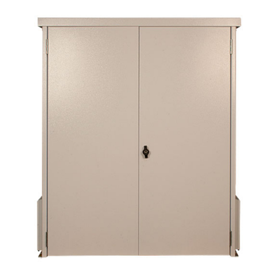
- Page 1 Magnum AC Coupled In a D3R battery box MND3RACCPLME 7/22/15...
-
Page 2: General Precautions
MND3RACCPLME (continued) SAVE THESE INSTRUCTIONS - These instructions contain important safety and operating instructions for the MidNite Solar Battery Enclosure Size B, D, D3R and E for residential and commercial applications. If you do not fully understand any of the concepts, terminology, or hazards outlined in these instructions, please refer installation to a qualified dealer, electrician or installer. - Page 3 Copyright ⓒ 2010, 2011 all rights reserved. MidNite Solar Inc. reserves the right to revise this document and to periodically make changes to the content hereof without obligation or organization of such revisions or changes unless required to do so by prior arrangement.
- Page 4 MND3RACCPLME (continued) MidNite Solar recommends that this system be installed by a professional electrician due to the interaction with the electrical service on the dwelling. Please consult all Local, State and federal codes that may apply to this install as well as acquire any permits that may be needed. This device is not intended to be relied on for life support.
- Page 5 MND3RACCPLME (continued) You will need to find the appropriate location to install the Battery box, both for wiring as well as stability. We recommend if it is to be installed outdoors you try to keep it out of direct sunlight. You will need to secure the box using the mounting holes in the feet.
- Page 6 15 amp 120/240VAC breaker in the AC coupled box. The Magnum inverter is limited in the capacity of grid tie it can handle. If the grid tie system is greater than 15 amps at 240VAC please contact customer service at MidNite Solar for help designing the system. P a g e...
- Page 7 MND3RACCPLME (continued) Shown below are the Buss Bars for step 1, this is where the feeder from the utility main panel will connect. The first picture shows the common AC Neutral as well as the Earth ground buss bar. These 2 buss bars will be used in all 3 steps.
- Page 8 MND3RACCPLME (continued) Buss bars for Step 2 AC Out to the Critical Loads panel. Buss bars for Step 3 AC in from the Grid Tie Inverter. P a g e 1 0 - 2 2 0 - 1 R E V : B...
- Page 9 MND3RACCPLME (continued) Below is a wiring diagram showing the AC wiring to be done in the field. P a g e 1 0 - 2 2 0 - 1 R E V : B...
- Page 10 4 batteries in and connect them in a series string for 24 vdc. We are recommending the Concorde PVX3050T 6 volt batteries for this. For other battery arrangements or larger battery banks please consult with customer service at MidNite Solar. NOTE: Never used Vented batteries in this system use only SEALED batteries..
- Page 11 MND3RACCPLME (continued) Now that all the wiring is done we need to power things up. We will start by powering the Magnum inverter on and checking the programming. Shown below is a close up shot of the breakers. Below is an explanation of what they all do and how you want them for Normal operation as well as the sequence for power up.
- Page 12 MND3RACCPLME (continued) At this point we need to turn the Large 250 amp breaker on (The one on the far right) to power up the Magnum inverter. After power up we strongly suggest going through the settings in the Remote for the Magnum to verify everything is set correctly.
- Page 13 MND3RACCPLME (continued) Push the CTRL Button, Turn the Select knob to show 01 AC In Control, Press the Select knob to Edit 01. Scroll the select knob to select “Auto Connect” and press the select knob again. Push the CTRL Button, Turn the Select knob to show 04 RTR Aux Relay.
-
Page 14: Testing The Setup
MND3RACCPLME (continued) TESTING THE SETUP After everything is set and everything appears to be in order we suggest running a test when you have time to watch the system through a cycle. To run the test Turn off the Inverter AC input breaker inside the AC Coupled box. - Page 15 (5) years. At its option, Midnite Solar will repair or replace at no charge any Midnite product that proves to be defective within such warranty period. This warranty shall not apply if the...
Need help?
Do you have a question about the MND3RACCPLME and is the answer not in the manual?
Questions and answers