
Related Manuals for National Instruments ATE Core Configurations


Summary of Contents for National Instruments ATE Core Configurations
- Page 1 ATE Core Configurations RMX-10011 User Manual ATE Core Configurations RMX-10011 User Manual October 2017 377138A-01...
- Page 2 11500 North Mopac Expressway Austin, Texas 78759-3504 USA Tel: 512 683 0100 For further support information, refer to the NI Services appendix. To comment on National Instruments documentation, refer to the National Instruments web site at ni.com/info enter the Info Code feedback...
- Page 3 National Instruments Corporation. National Instruments respects the intellectual property of others, and we ask our users to do the same. NI software is protected by copyright and other intellectual property laws. Where NI software may be used to reproduce software or other materials belonging to others, you may use NI software only to reproduce materials that you may reproduce in accordance with the terms of any applicable license or other legal restriction.
- Page 4 ™ The ExpressCard word mark and logos are owned by PCMCIA and any use of such marks by National Instruments is under license. The mark LabWindows is used under a license from Microsoft Corporation. Windows is a registered trademark of Microsoft Corporation in the United States and other countries.
- Page 5 Operation of this hardware in a residential area is likely to cause harmful interference. Users are required to correct the interference at their own expense or cease operation of the hardware. Changes or modifications not expressly approved by National Instruments could void the user’s right to operate the hardware under the local regulatory rules.
-
Page 6: Table Of Contents
Walls and Rear Door ..................3-4 Grounding......................3-4 Chapter 4 System Bring Up System Hardware......................4-1 Power Entry Panel (PEP)..................4-1 Main Disconnect and Circuit Breakers............. 4-2 USB Ports ......................4-3 Ethernet Port ..................... 4-3 © National Instruments | vii... - Page 7 Contents Connecting to a Network .................. 4-3 Removing Power....................4-3 Power Distribution Unit (PDU) ................4-3 Emergency Power Off (EPO) Panel ................. 4-4 Emergency Power Off (EPO) Button ............... 4-4 Main Power Switch...................4-4 Temperature Controller..................4-4 Uninterruptable Power Supply (UPS)...............4-4 System Block Diagrams....................
-
Page 8: Overview
NI and third party instrumentation layout and are meant to be customized for a specific application. Nomenclature The ATE Core Configurations are uniquely identified by the voltage and power input type of the system. Refer to Appendix A, Specifications for more details about ATE Core Configurations power input ratings. -
Page 9: Core System Layout
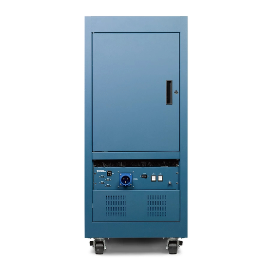
Chapter 1 Introduction Core System Layout The following figures show the locations of the ATE Core Configurations hardware. The following figures show a 24 U Low Power configuration. Note Figure 1-2. Front and Side View of ATE Core Configurations Industrial Casters... - Page 10 ATE Core Configurations RMX-10011 User Manual Figure 1-3. Rear and Side View of ATE Core Configurations 4U Air Inlet Panel Removable Rear Door 3U Power Entry Panel Fan Panel 1U Brush Cable Entry Side Panel © National Instruments | 1-3...
- Page 11 Chapter 1 Introduction Figure 1-4. Side View of ATE Core Configurations Cable Management Mounting Rails Power Distribution Unit Figure 1-5. Cutaway View of Ethernet Switch Location Ethernet Switch Cable Management 1-4 | ni.com...
-
Page 12: Installation And Configuration
Installation and Configuration Packaging Information ATE Core Configurations ship from the factory in a shipping crate. The shipping crate can negotiate ramps and small bumps such as door thresholds. Carefully inspect the shipping crate and the rack for damage. Check for visible damage to the metal work. -
Page 13: Crate Dimensions
Chapter 2 Installation and Configuration Crate Dimensions Figure 2-2. 24U Crate Dimensions Dimensions are in millimeters (inches) 673 (26.5) 908 (35.75) 991 (39) 1031 (40.56) 2-2 | ni.com... -
Page 14: Required Tools
Dimensions are in millimeters (inches) 673 (26.5) 908 (35.75) 991 (39) 1031 (40.56) Required Tools The ATE Core Configurations do not require special tools. Ensure that you have the following standard tools to bring up, maintain, and troubleshoot. • Screwdrivers – Standard Head •... -
Page 15: Hallway And Door Width Requirements
Chapter 2 Installation and Configuration Hallway and Door Width Requirements Verify that all doors, elevators, and passageways en route to the final location are large enough to allow passage of the crated system. The crated system requires the use of a floor jack or forklift to engage the pallet and lift the crated system. -
Page 16: Mechanical Stability And Loading
ATE Core Configurations RMX-10011 User Manual Remove the removable block at the top of the ramp. Roll the rack out of the crate using the ramp. Remove VpCI bag. Move the system to its designated area. Mechanical Stability and Loading Precautions were taken in designing your rack configuration to ensure physical stability of the system. -
Page 17: Site Requirements
V erify that you have met all requirements before powering on. Power Connection The ATE Core Configurations contains a Power Entry Panel for AC Mains and a corresponding power plug. The system must meet the following power connection requirements: •... -
Page 18: Cooling Requirements
ATE Core Configurations RMX-10011 User Manual Cooling Requirements The ATE Core Configurations ship with several features to help facilitate proper cooling, but due to instrumentation layout, third party devices, cabling, and mass interconnect, it is important to do a thorough thermal assessment of the final system assembly. -
Page 19: Safety Information
NI assumes no liability for the customer’s failure to comply with these requirements. Using the ATE Core Configurations, or any component within, in a manner not Note specified by the manufacturer may reduce or eliminate equipment and/or personnel safety measures. -
Page 20: Removing Power
Chapter 3 Safety Information Table 3-2. Mid Power Configuration Power Cables Part Number Description 785718-01 AC, Single Phase IEC 60309, 2P+E, Receptacle, to IEC 60309, 2P+E, Plug, 2.5 m 785719-01 AC, Single Phase IEC 60309, 2P+E, Receptacle, to NEMA L6-30, 2.5 m 785735-01 IEC 60309, 2P+E, pin and sleeve (connector only) Table 3-3. -
Page 21: Operator Safety Information
Safety Features Safety Shutoff Thermostats ATE Core Configurations has two safety shutoff thermostats (or four if the system is configured with a UPS) on the interior surface of the fan cooling panel located at the top of the rack. The thermostats are configured to shut the system off in the event the rack is unable to provide adequate cooling, preventing a safety hazard to the user. -
Page 22: Emergency Power Off (Epo) Panel
Chapter 3 Safety Information The thermostats are configured so they will not activate under normal Note operating conditions, recommended power levels, cooling configuration, and ambient environment. If the thermostats are triggered and no equipment fault can be found in the system, the system may be configured in such a way that there is an extreme thermal load in a small area of the system. -
Page 23: System Bring Up
Your exact configuration may consist of all the required elements and any Note optional components. System Hardware Power Entry Panel (PEP) There are four distinct power configurations available with the ATE Core Configurations: • Low Power • Mid Power •... -
Page 24: Main Disconnect And Circuit Breakers
Chapter 4 System Bring Up Figure 4-1. Front View of Power Entry Panel NATIONAL INSTRUMENTS Power Inlet Connector Ethernet Port Individual Outlet Breakers (Mid Power Only) Main Breaker USB Ports Ground Stud Mid Power PEP shown, components are representative. Note Figure 4-2. -
Page 25: Usb Ports
ATE Core Configurations RMX-10011 User Manual USB Ports The Power Entry Panel has two USB ports which provide access to extension cables within the rack. These cables can be connected to provide external access to USB ports on internal equipment. -
Page 26: Emergency Power Off (Epo) Panel
EPO mechanisms are included on the ATE Core Configurations to simplify connectivity and inhibit power switching. Operators may use the EPO to reset a system in an error state, prevent damage to a DUT, or even prevent harm to themselves. -
Page 27: System Block Diagrams
ATE Core Configurations RMX-10011 User Manual System Block Diagrams Figure 4-4. Low Power System Block Diagram Safety Shutoff Thermostats Emergency Power Off (EPO) Panel Uninterruptable Power Entry Panel Power Distribution Power Supply (UPS) Rack Fans (PEP) Unit (PDU) [Optional] PDU connects directly to the PEP if there is not a UPS installed. -
Page 28: Power States
Chapter 4 System Bring Up Figure 4-6. High Power System Block Diagram Safety Shutoff Thermostats Emergency Power Off (EPO) Panel 3 Phase 3 Phase Power Distribution Power Entry Panel Unit (PDU) Rack Fans (PEP) Single Phase Outputs Power States The ATE Core Configuration system has multiple states of operation: •... -
Page 29: Powering On
ATE Core Configurations RMX-10011 User Manual Powering On Complete the following steps to power on the ATE Core Configurations. Do not proceed unless qualified personnel has reviewed all installation Caution instructions, written warnings, and cautions. Verify that the Power Inlet Connector on the Power Entry Panel is connected to AC Mains. -
Page 30: Maintenance
Use only enough moisture to dampen the cloth. Do not wash the front- or rear-panel connectors or switches. Cover these Caution components while cleaning the ATE Core Configurations. Do not use harsh chemical cleaning agents; they may damage the system. Caution Avoid chemicals that contain benzene, toluene, xylene, acetone, or similar solvents. -
Page 31: Cleaning Air Intake Filters
Clean the air intake filters using warm water with a mild soap solution, then air dry the filters to remove moisture. Avoid installing wet filters into the ATE Core Configurations. V erify that Caution the filters are thoroughly dry before re-installing. -
Page 32: Calibration
PDU, EPO Panel, and the Moxa Ethernet Switch. Calibration Calibration for each ATE Core Configurations component is available and can be coordinated through your local sales representative, or by contacting the designated support resources. Table 5-4. Component Repair and Calibration for ATE Core Configurations... -
Page 33: Appendix A Specifications
The outlet circuit breaker(s) on the power entry panels PEP-116 and PEP-130 for Low and Mid power ATE Core Configurations are rated for an impact energy level of IK06 (1J), when tested with a direct vertical impact per IEC 61010-1, 3rd Ed., Table 15 and Clause 8.2. - Page 34 Appendix A Specifications 40U Rack Dimensions System height............81.5 in (2,070.1 mm) System width.............23 in. (584.2 mm) System depth.............31.5 in. (800 mm) Mountable depth ..........29.5 in. (749.3 mm) Max static load..........1,000 lb. (453.5 kg), evenly distributed across each caster Environment Maximum altitude..........2,000 m (800 mbar) Allowable power dissipation is decreased by 25% at 2000 m.
- Page 35 ATE Core Configurations RMX-10011 User Manual Acoustic Emissions Sound Pressure Level (at Operator Position) High speed fan panel ........92 dBA max. at operator position 85 dBA max. at bystander position (1 m away) All personnel must use hearing protection while the RMX-10011 system Caution with a high speed fan panel is in operation.
- Page 36 Appendix A Specifications High Power 3-Phase Wye (ATE-3W16H-A, ATE-3W16F-A) Rating Input..............220/380 to 240/415 VAC, 16 A, 50/60 Hz, 3P+N+PE, 3 PDU Output (each phase) ......220 to 240 VAC, 10 A maximum per C13 receptacle, 16 A maximum per C19 receptacle, 50/60 Hz (single phase) Bank J1 ..........15.5 A with low speed fan panel 14.4 A with high speed fan panel...
- Page 37 Equipment with ambient temperature ratings below 45 °C have not been validated to work with the ATE Core Configurations systems. If equipment rated below 45 °C is used, care must be taken to ensure the operating conditions of the equipment are not violated.
- Page 38 Appendix A Specifications Table A-1. Low Power (100 to 120 VAC, 16 A, 50/60 Hz Input) (Watts) Low Speed Fan Panel High Speed Fan Panel Max. Internal Temp Max. Internal Temp 24U or 40 U Configurations 45 °C 50 °C 45 °C 50 °C 40 °C Ambient...
- Page 39 ATE Core Configurations RMX-10011 User Manual Table A-3. Mid Power (200 to 240 VAC, 24 A, 50/60 Hz Input) (Watts) Low Speed Fan Panel High Speed Fan Panel Max. Internal Temp Max. Internal Temp 24U or 40 U Configurations 45 °C 50 °C...
- Page 40 Appendix A Specifications Table A-5. High Power (3 Phase Wye, 220/380 to 240/415 VAC, 16 A, 50/60 Hz Input) (Watts) Low Speed Fan Panel High Speed Fan Panel Max. Internal Temp Max. Internal Temp 24U or 40 U Configurations 45 °C 50 °C 45 °C 50 °C...
- Page 41 ATE Core Configurations RMX-10011 User Manual In the United States (per FCC 47 CFR), Class A equipment is intended for use Note in commercial, light-industrial, and heavy-industrial locations. In Europe, Canada, Australia and New Zealand (per CISPR 11) Class A equipment is intended for use only in heavy-industrial locations.
- Page 42 At the end of the product life cycle, all products must be sent to EU Customers a WEEE recycling center. For more information about WEEE recycling centers, National Instruments WEEE initiatives, and compliance with WEEE Directive 2002/96/EC on Waste and Electronic Equipment, visit ni.com/environment/...
-
Page 43: Appendix B Internal Power Cables
Internal Power Cables This appendix lists the internal power cables for the ATE Core Configurations. Table B-1. RMX-10011 Internal Power Cables Part Number Description 785707-01 AC, IEC C20 to NEMA 5-20R, 125 V, 16 A, 0.25 m (US) 785708-01 AC, IEC C19 to NEMA 5-20P, 125 V, 16 A, 2.5 m (US) 785709-01 AC, IEC C20 to IEC C13, 240 V, 10 A (EU), 16 A (UL), 1.5 m (US, EU) - Page 44 Appendix B Internal Power Cables Table B-1. RMX-10011 Internal Power Cables (Continued) Part Number Description 785727-02 AC, NEMA 5-20P to Bare Wire, 125 V, 20 A, 2.5m (US) 785892-01 AC, IEC C14 to Bare Wire, 240 V, 10 A, 1.5 m (US) 785892-02 AC, IEC C14 to Bare Wire, 240 V, 10 A, 2.5 m (US) B-2 | ni.com...
- Page 45 NI Services National Instruments provides global services and support as part of our commitment to your success. Take advantage of product services in addition to training and certification programs that meet your needs during each phase of the application life cycle; from planning and development through deployment and ongoing maintenance.
- Page 46 Appendix C NI Services • Training and Certification—The NI training and certification program is the most effective way to increase application development proficiency and productivity. Visit for more information. ni.com/training – The Skills Guide assists you in identifying the proficiency requirements of your current application and gives you options for obtaining those skills consistent with your time and budget constraints and personal learning preferences.
- Page 47 Symbols ° Degrees. ≥ Equal or greater than. ≤ Equal or less than. Percent. Amperes. Alternating current. ANSI American National Standards Institute. Auto Automatic fan speed control. American Wire Gauge. © National Instruments | G-1...
- Page 48 Glossary backplane An assembly, typically a printed circuit board, with connectors and signal paths that bus the connector pins. Bayonet Neill Concelman connector; a commonly used coaxial connector. Celsius. Cubic feet per minute. Code of Federal Regulations. Centimeters. CompactPCI An adaptation of the Peripheral Component Interconnect (PCI) Specification 2.1 or later for industrial and/or embedded applications requiring a more robust mechanical form factor than desktop PCI.
- Page 49 ATE Core Configurations RMX-10011 User Manual efficiency Ratio of output power to input power, expressed as a percentage. Electronic Industries Association. Electromagnetic Compatibility. Electromagnetic Interference. Federal Communications Commission. filler panel A blank module front panel used to fill empty slots in the chassis.
- Page 50 Glossary Inches. inhibit To turn off. jitter A measure of the small, rapid variations in clock transition times from their nominal regular intervals. Units: seconds RMS. Kilograms. Kilometers. Pounds. Light emitting diode. line regulation The maximum steady-state percentage that a DC voltage output will change as a result of a specified change in input AC voltage (step change from 90 to 132 VAC or 180 to 264 VAC).
- Page 51 ATE Core Configurations RMX-10011 User Manual MTBF Mean time between failure. MTTR Mean time to repair. NEMA National Electrical Manufacturers Association. National Instruments. power supply shuttle A removable module that contains the chassis power supply. PCI eXtensions for Instrumentation. PXI_CLK10 10 MHz PXI system reference clock.
- Page 52 Glossary system reference A 10 MHz clock, also called PXI_CLK10, that is distributed to clock all peripheral slots in the chassis, as well as a BNC connector on the rear of chassis labeled 10 MHz REF OUT. The system reference clock can be used for synchronization of multiple modules in a measurement or control system.
- Page 53 B-1 specifications, A-8 introduction site requirements, 2-6 nomenclature, 1-1 specifications, A-1 overview, 1-1 CE compliance, A-9 dimensions, A-1, A-2 electrical, A-2 loading, 2-5 electromagnetic compatibility, A-8 environment, A-2 mechanical, A-1 safety, A-8 © National Instruments | I-1...
- Page 54 Index system block diagrams, 4-5 bring up, 4-1 hardware, 4-1 layout, 1-2 uncrating, 2-4 temperature controller, 3-4, 4-4 thermal load, A-5 thermostats, 3-3 uncrating, 2-4 uninterruptable power supply (UPS), 4-4 USB ports, 4-3 I-2 | ni.com...
Need help?
Do you have a question about the ATE Core Configurations and is the answer not in the manual?
Questions and answers