Table of Contents
Advertisement
Available languages
Available languages
Advertisement
Table of Contents

Related Manuals for ATT NUSSBAUM COMBI LIFT 4.40 S


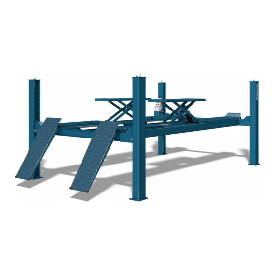
Summary of Contents for ATT NUSSBAUM COMBI LIFT 4.40 S
- Page 1 HYMAX II 4000 S COMBI LIFT 4.40 S A HYMAX II 4000 S A COMBI LIFT 4.40 S PLUS HYMAX II 4000 S PLUS COMBI LIFT 4.40 S PLUS AMS HYMAX II 4000 S PLUS AMS Made Serien Nr. / Serial No.: Germany...
- Page 2 OPI_COMBI LIFT 4.40 S PLUS AMS_V3.0_DE-EN...
-
Page 3: Table Of Contents
DEUTSCH Einleitung ___________________________________________5 Radfreiheber ________________________________ 97 AufstelIungsprotokolI _________________________________6 Anheben aus der Sicherheitsklinke ____________ 97 Übergabeprotokoll __________________________________7 Senken des Fahrzeuges ______________________ 97 RFH Schienenhöhenausgleich ________________ 98 Allgemeine Information ___________________ 8 5.10 Sicherheitsschalter unter der Fahrschiene _____ 98 Aufstellung und Prüfung der Anlage ____________8 Verhalten im Störungsfall _________________ 98 Gefährdungshinweise __________________________8 Auffahren auf ein Hindernis ___________________ 99... - Page 4 Maintenance and care of the system ____ 141 Selecting the anchors _______________________ 144 System maintenance plan __________________ 141 Assembly ___________________________________ 144 Daily, as required or visible damage _________ 141 Set up and anchoring the lift ________________ 144 Maintenance 1 x per year ___________________ 141 Electrical connections ______________________ 145 Maintenance every 2 years _________________ 142 Loose/broken cable switch __________________ 145...
-
Page 5: Einleitung
DEUTSCH Original Einleitung Organisatorische Maßnahmen Nussbaum Produkte sind ein Ergebnis langjähriger • Die Bedienungsanleitung ist ständig am Einsatzort Erfahrung. Der hohe Qualitätsanspruch und das der Anlage griffbereit aufzubewahren. überlegene Konzept garantieren Ihnen Zuverlässig- • Ergänzend zur Betriebsanleitung sind allgemein- keit, eine lange Lebensdauer und den wirtschaftli- gültige gesetzliche und sonstige verbindliche Re- chen Betrieb. -
Page 6: Aufsteliungsprotokoli
AufstelIungsprotokolI Nach erfolgter Aufstellung, dieses Blatt komplett ausfüllen, unterschreiben, kopieren und das Original innerhalb einer Woche an den Hersteller senden. E-Mail: info@nussbaum-group.de Fax: +49 78 53-87 87 Die Anlage mit der Seriennummer _________________________ wurde am __________________________ bei der Firma _____________________________________________ in __________________________________ aufgestellt, auf Funktion und Sicherheit überprüft und in Betrieb genommen. -
Page 7: Übergabeprotokoll
Übergabeprotokoll Die Anlage ______________________________________________ mit der Seriennummer ____________________________________ wurde am __________________________ bei der Firma _____________________________________________ in __________________________________ aufgestellt, auf Funktion und Sicherheit überprüft und in Betrieb genommen. Nachfolgend aufgeführte Personen (Bediener) wurden nach Aufstellung der Hebebühne durch einen ge- schulten Monteur des Herstellers oder eines Vertragshändlers (Sachkundiger) in die Handhabung des Hub- gerätes eingewiesen. -
Page 8: Allgemeine Information
Allgemeine Information Die Technische Dokumentation enthält wichtige In- formationen zum sicheren Betrieb und zur Erhaltung der Funktionssicherheit der Anlage. • Zum Nachweis der Aufstellung der Anlage ist das Formular Aufstellungsprotokoll unterzeichnet an den Hersteller zu senden. • Zum Nachweis der einmaligen, regelmäßigen und außerordentlichen Sicherheitsüberprüfungen ent- hält dieses Prüfbuch Formulare. -
Page 9: Stammblatt Der Anlage
Stammblatt der Anlage Hersteller Nussbaum Custom Lifts GmbH Hertz Str. 6 D-77694 Kehl-Sundheim Verwendungszweck Die Hebebühne ist ein Hebewerkzeug für das Anheben von Kraftfahrzeugen bis zu einem Gesamtgewicht von 4.500 kg bei einer maximalen Lastverteilung von 2:1 in Auffahrrichtung oder entgegen der Auffahrrich- tung. -
Page 10: Konformitätserklärungen
Konformitätserklärungen OPI_COMBI LIFT 4.40 S PLUS AMS_V3.0_DE-EN... -
Page 11: Technische Information
Technische Information Sicherheitseinrichtungen • Totmann Steuerung Technische Daten Beim Loslassen eines Tasters stoppt die Bewegung der Hebebühne. Tragfähigkeit Anlage • Wendeschalter mit Vorhängeschlosseinrichtung ohne Radfreiheber 4.500 kg Sicherung gegen unbefugte Benutzung. mit Radfreiheber (opti- • Überdruckventil onal) 4.000 kg Sicherung des Hydrauliksystemes gegen Über- druck. -
Page 12: Datenblätter
Datenblätter 3.3.1 COMBI LIFT 4.40 S - HYMAX II 4000 S OPI_COMBI LIFT 4.40 S PLUS AMS_V3.0_DE-EN... - Page 13 3.3.2 COMBI LIFT 4.40 S AMS - HYMAX II 4000 S AMS OPI_COMBI LIFT 4.40 S PLUS AMS_V3.0_DE-EN...
- Page 14 3.3.3 COMBI LIFT 4.40 S PLUS - HYMAX II 4000 S PLUS OPI_COMBI LIFT 4.40 S PLUS AMS_V3.0_DE-EN...
- Page 15 3.3.4 COMBI LIFT 4.40 S PLUS AMS - HYMAX II 4000 S PLUS AMS OPI_COMBI LIFT 4.40 S PLUS AMS_V3.0_DE-EN...
-
Page 16: Fundamentplan
Fundamentplan OPI_COMBI LIFT 4.40 S PLUS AMS_V3.0_DE-EN... -
Page 17: Hydraulikplan
Hydraulikplan 3.5.1 ohne Radfreiheber 0.12 0.11 0.7mm 0 .9 0.10 0 .8 0 .7 0 .5 0 .3 0 .4 0 .2 0 .1 V 0 0 440H01213 ÖLBEHÄLTER 155211 DRUCKBEGRENZUNGSVENTIL 980201 ÖLFILTER 600161 SENKBREMSE 992658 MOTOR 0.10 130053 RÜCKSCHLAGVENTIL 980340 ZAHNRADPUMPE 0.11... - Page 18 3.5.2 mit Radfreiheber 1.0mm 1.0mm 0.17 0.17 0.17 0.12 0.11 0.7mm 0 .9 0.10 0 .8 0 .7 0 .5 0 .3 0 .4 0 .2 0 .1 V 0 0 440H01213 ÖLBEHÄLTER 600161 SENKBREMSE 980201 ÖLFILTER 0.10 130053 RÜCKSCHLAGVENTIL 992658 MOTOR 0.11...
-
Page 19: Elektroschaltplan
Elektroschaltplan Sicherheitsprüfung und Schutzmaßnahmen Der Schaltschrank wurde unter Beachtung der an- Erdung nach örtlichen Vorschriften erkannten Regeln der Technik nach VDE0100/0113 Vor Inbetriebnahme prüfen, ob Motornennstrom sowie der Unfallverhütungsvorschrift VBG4 (elek- mit Motorschutzrelais übereinstimmt. Alle Klemm- trische Anlagen und Betriebsmittel) gefertigt bzw. stellen auf ordnungsgemäße Verbindung und alle errichtet und geprüft. - Page 20 3.6.1 3 x 230 V OPI_COMBI LIFT 4.40 S PLUS AMS_V3.0_DE-EN...
- Page 21 OPI_COMBI LIFT 4.40 S PLUS AMS_V3.0_DE-EN...
- Page 22 OPI_COMBI LIFT 4.40 S PLUS AMS_V3.0_DE-EN...
- Page 23 OPI_COMBI LIFT 4.40 S PLUS AMS_V3.0_DE-EN...
- Page 24 ...
- Page 25 ...
- Page 26 OPI_COMBI LIFT 4.40 S PLUS AMS_V3.0_DE-EN...
- Page 27 OPI_COMBI LIFT 4.40 S PLUS AMS_V3.0_DE-EN...
- Page 28 3.6.2 3 x 400 V OPI_COMBI LIFT 4.40 S PLUS AMS_V3.0_DE-EN...
- Page 29 OPI_COMBI LIFT 4.40 S PLUS AMS_V3.0_DE-EN...
- Page 30 OPI_COMBI LIFT 4.40 S PLUS AMS_V3.0_DE-EN...
- Page 31 OPI_COMBI LIFT 4.40 S PLUS AMS_V3.0_DE-EN...
- Page 32 ...
- Page 33 ...
- Page 34 OPI_COMBI LIFT 4.40 S PLUS AMS_V3.0_DE-EN...
- Page 35 OPI_COMBI LIFT 4.40 S PLUS AMS_V3.0_DE-EN...
- Page 36 3.6.3 3 x 230 V RFH OPI_COMBI LIFT 4.40 S PLUS AMS_V3.0_DE-EN...
- Page 37 OPI_COMBI LIFT 4.40 S PLUS AMS_V3.0_DE-EN...
- Page 38 OPI_COMBI LIFT 4.40 S PLUS AMS_V3.0_DE-EN...
- Page 39 OPI_COMBI LIFT 4.40 S PLUS AMS_V3.0_DE-EN...
- Page 40 ...
- Page 41 ...
- Page 42 OPI_COMBI LIFT 4.40 S PLUS AMS_V3.0_DE-EN...
- Page 43 OPI_COMBI LIFT 4.40 S PLUS AMS_V3.0_DE-EN...
- Page 44 3.6.4 3 x 400 V RFH OPI_COMBI LIFT 4.40 S PLUS AMS_V3.0_DE-EN...
- Page 45 OPI_COMBI LIFT 4.40 S PLUS AMS_V3.0_DE-EN...
- Page 46 OPI_COMBI LIFT 4.40 S PLUS AMS_V3.0_DE-EN...
- Page 47 OPI_COMBI LIFT 4.40 S PLUS AMS_V3.0_DE-EN...
- Page 48 ...
- Page 49 ...
- Page 50 OPI_COMBI LIFT 4.40 S PLUS AMS_V3.0_DE-EN...
- Page 51 OPI_COMBI LIFT 4.40 S PLUS AMS_V3.0_DE-EN...
- Page 52 3.6.5 3 x 400 V (Rechtslenker) OPI_COMBI LIFT 4.40 S PLUS AMS_V3.0_DE-EN...
- Page 53 OPI_COMBI LIFT 4.40 S PLUS AMS_V3.0_DE-EN...
- Page 54 OPI_COMBI LIFT 4.40 S PLUS AMS_V3.0_DE-EN...
- Page 55 OPI_COMBI LIFT 4.40 S PLUS AMS_V3.0_DE-EN...
- Page 56 ...
- Page 57 ...
- Page 58 ...
- Page 59 OPI_COMBI LIFT 4.40 S PLUS AMS_V3.0_DE-EN...
- Page 60 OPI_COMBI LIFT 4.40 S PLUS AMS_V3.0_DE-EN...
- Page 61 3.6.6 3 x 400 V (mit Deckenabschaltung) OPI_COMBI LIFT 4.40 S PLUS AMS_V3.0_DE-EN...
- Page 62 OPI_COMBI LIFT 4.40 S PLUS AMS_V3.0_DE-EN...
- Page 63 OPI_COMBI LIFT 4.40 S PLUS AMS_V3.0_DE-EN...
- Page 64 OPI_COMBI LIFT 4.40 S PLUS AMS_V3.0_DE-EN...
- Page 65 ...
- Page 66 ...
- Page 67 OPI_COMBI LIFT 4.40 S PLUS AMS_V3.0_DE-EN...
- Page 68 OPI_COMBI LIFT 4.40 S PLUS AMS_V3.0_DE-EN...
- Page 69 3.6.7 3 x 400 V RFH (Rechtslenker) OPI_COMBI LIFT 4.40 S PLUS AMS_V3.0_DE-EN...
- Page 70 OPI_COMBI LIFT 4.40 S PLUS AMS_V3.0_DE-EN...
- Page 71 OPI_COMBI LIFT 4.40 S PLUS AMS_V3.0_DE-EN...
- Page 72 OPI_COMBI LIFT 4.40 S PLUS AMS_V3.0_DE-EN...
- Page 73 ...
- Page 74 ...
- Page 75 ...
- Page 76 OPI_COMBI LIFT 4.40 S PLUS AMS_V3.0_DE-EN...
- Page 77 OPI_COMBI LIFT 4.40 S PLUS AMS_V3.0_DE-EN...
- Page 78 3.6.8 3 x 400 V RFH (mit Deckenabschaltung) OPI_COMBI LIFT 4.40 S PLUS AMS_V3.0_DE-EN...
- Page 79 OPI_COMBI LIFT 4.40 S PLUS AMS_V3.0_DE-EN...
- Page 80 OPI_COMBI LIFT 4.40 S PLUS AMS_V3.0_DE-EN...
- Page 81 OPI_COMBI LIFT 4.40 S PLUS AMS_V3.0_DE-EN...
- Page 82 OPI_COMBI LIFT 4.40 S PLUS AMS_V3.0_DE-EN...
- Page 83 ...
- Page 84 ...
- Page 85 OPI_COMBI LIFT 4.40 S PLUS AMS_V3.0_DE-EN...
- Page 86 OPI_COMBI LIFT 4.40 S PLUS AMS_V3.0_DE-EN...
- Page 87 3.6.9 1 x 230 V RFH OPI_COMBI LIFT 4.40 S PLUS AMS_V3.0_DE-EN...
- Page 88 OPI_COMBI LIFT 4.40 S PLUS AMS_V3.0_DE-EN...
- Page 89 OPI_COMBI LIFT 4.40 S PLUS AMS_V3.0_DE-EN...
- Page 90 OPI_COMBI LIFT 4.40 S PLUS AMS_V3.0_DE-EN...
- Page 91 ...
- Page 92 ...
- Page 93 OPI_COMBI LIFT 4.40 S PLUS AMS_V3.0_DE-EN...
- Page 94 OPI_COMBI LIFT 4.40 S PLUS AMS_V3.0_DE-EN...
-
Page 95: Sicherheitsbestimmungen
Sicherheitsbestimmungen • Die Aufstellung der serienmäßigen Hebebühne in explosionsgefährdeten Betriebsstätten und Beim Umgang mit Anlagen sind die gesetzlichen feuchten Räumen (z. B. Waschhallen) ist verbo- Unfallverhütungsvorschriften nach BGG 945: Prü- ten. fung von Hebebühnen; BGR 500 Betreiben von An- • Wir weisen in unseren Plänen auf die Mindestan- lagen;... -
Page 96: Bedienungsanleitung
Bedienungsanleitung Positionierung des Fahrzeuges • Die Hebebühne muss vor dem Auffahren des Fahr- zeuges vollständig abgesenkt sein und darf nur in Während der Handhabung der Anla- der dafür vorgesehenen Richtung erfolgen. ge sind die Sicherheitsbestimmungen • Das Fahrzeug auf die Fahrschienen in Längs- und unbedingt einzuhalten. -
Page 97: Absetzen In Die Sicherheitsklinke
Absetzen in die Sicherheitsklinke • Fahrzeug anheben bis Räder frei sind; Taster „HE- • Durch Drücken des Tasters „Absetzen in Klinke“ BEN” (12) drücken, anschließend den sicheren (15) wird die Hebebühne in die nächst mögliche Sitz des Fahrzeuges auf der Hebebühne überprü- Klinke abgesetzt. -
Page 98: Rfh Schienenhöhenausgleich
RFH Schienenhöhenausgleich Problem: Hebebühne lässt sich nicht anheben Bei längerem Dauerbetrieb des Radfreihebers ohne mögliche Ursachen: Abhilfe: Erreichen der untersten Position, kann es funktions- bedingt zu einem Ungleichlauf der Auffahrschienen keine Stromversorgung Prüfen der Stromversor- kommen. Im Normalfall stellt sich die Höhengleich- gung heit nach längerer Wartezeit (Abkühlen des Öles) wieder ein. -
Page 99: Auffahren Auf Ein Hindernis
Problem: Hebebühne lässt sich nicht absenken Stromausfall kann Notablass vorgenommen werden, wenn Sicher- mögliche Ursachen: Abhilfe: heitsklinken (24) nicht eingerastet sind. Daher sollte das Ende des Stromausfalles abge- Hebebühne sitzt auf Hebebühne anheben wartet werden. Bei Ventildefekt kann die einge- Hindernis auf und Hindernis entfernen. - Page 100 19 Aufschraubkappe mit Flügelschraube 20 Ventil MV4 18 Aufschraubkappe mit Innensechskantschraube 21 Ventil MV1 Diesen Vorgang an beiden Seiten vornehmen 22 Ventil MV2 um eine gleichmäßige Absenkung des Fahr- 23 3er Innensechskantschlüssel zeuges zu erreichen. 6.2.3 Hebebühne ohne Radfreiheber Wenn die beiden Radfreiheber Ventile MV4 und Bevor die Hebebühne über den Notablass abge- MV5 durch die Flügelschrauben (19) geöffnet wur- senkt werden kann, müssen die Sicherheitsklinken...
-
Page 101: Wartung Und Pflege Der Anlage
Wartung und Pflege der Anlage Vor einer Wartung sind alle Vorberei- tungen zu treffen, dass bei Wartungs- und Reparaturarbeiten an der Huban- lage keine Gefahr für Leib und Leben und Beschädigungen von Gegenstän- den bestehen. Bei Entwicklung und Produktion von Nußbaum Pro- dukten wird auf Langlebigkeit und Sicherheit Wert gelegt. - Page 102 7.1.1 Täglich, bei Bedarf oder sichtbarer Be- Hydraulikleitungen sind dabei unbedingt auf schädigung mögliche Quetschstellen zu prüfen. Diese betrof- fenen Leitungen müssen ausgetauscht werden. • Zustand des Typenschildes, Tragfähigkeitsanga- Ansonsten sind Druckschläuche nach Bedarf, je- ben und Aufkleber prüfen. Bei Beschädigungen doch spätestens nach 6 Jahren auszutauschen.
-
Page 103: Reinigung Und Pflege Der Anlage
7.1.3 Wartung alle 2 Jahre Je länger Straßenstaub, Streusalz und andere ag- Das Hydrauliköl sollte nach Herstellerangaben im gressive Ablagerungen auf der Hebebühne haften normalen Betrieb mindestens alle zwei Jahre ge- bleiben desto schädlicher ist ihre Wirkung. wechselt werden. Verschiedenste Umgebungsein- Wie oft die Anlage gereinigt werden soll hängt un- flüsse z. B. Standort, Temperaturschwankungen, in- ter anderem von der Häufigkeit der Benutzung, von... -
Page 104: Inbetriebnahme
• Für elektrischen Standardanschluss • Querträger lösen und entfernen bauseits 3 ~/N + PE, 400 V, 50 Hz bereitzustellen. • Hebebühne an den neuen Aufstellungsort trans- Die Zuleitung ist gemäß VDE 0100 mit 16 Ampere portieren träge abzusichern. Der Mindestleiterquerschnitt •... - Page 105 Vor dem Aufstellen der Hebebühne ist ein ausrei- • Die Säulen an den Enden der Querträger positio- chendes Fundament durch den Betreiber nach- nieren. zuweisen oder zu erstellen. Hierzu ist ein normal • Seile durch die Enden der Querträger ziehen und bewehrter Betonboden mit einer Güte von min.
-
Page 106: Elektrischer Anschluss
Elektrischer Anschluss Fahrbahnniveau auf Ebenheit zueinander über- • Für den elektrischen Anschluss (siehe auch Kapitel prüfen. 15 Elektroschaltplan) ist bauseits 3~/N + PE, 400 V, • Die Auffahrschienen durch Verstellen der Befe- 50 Hz, Absicherung 16 Ampere träge bereitzustel- stigungsschrauben der Klinkenleisten (9) auf der len. -
Page 107: Sicherheitsüberprüfung
Sicherheitsüberprüfung Die Sicherheitsüberprüfung ist zur Gewährleistung der Betriebssicherheit der Hubanlage erforderlich. Sie ist durchzuführen: 1. Vor der ersten Inbetriebnahme nach dem Auf- stellen der Hubanlage Verwenden Sie das Formblatt „Einmalige Sicher- heitsüberprüfung“ 2. Nach der ersten Inbetriebnahme regelmäßig in Abständen von längstens einem Jahr Verwenden Sie das Formblatt „Regelmäßige Si- cherheitsüberprüfung“... -
Page 108: Einmalige Sicherheitsprüfung Vor Inbetrieb- Nahme
Einmalige Sicherheitsprüfung vor Inbetrieb nahme Kopieren, Ausfüllen und beim Prüfbuch belassen Seriennummer: _________________________________ Prüfschritt Mängel Nach- Bemerkung Ordnung Fehlt prüfung □ □ □ Typenschild .................._______________________________ □ □ □ Bedienungsanleitung ................. _______________________________ □ □ □ Aufkleber (z. B. Warnkennzeichnung) ...... - Page 109 Regelmäßige Sicherheitsprüfung und Wartung Kopieren, Ausfüllen und beim Prüfbuch belassen Seriennummer: _________________________________ Prüfschritt Mängel Nach- Bemerkung Ordnung Fehlt prüfung □ □ □ Typenschild .................._______________________________ □ □ □ Bedienungsanleitung ................. _______________________________ □ □ □ Aufkleber (z. B. Warnkennzeichnung) ......
- Page 110 Regelmäßige Sicherheitsprüfung und Wartung Kopieren, Ausfüllen und beim Prüfbuch belassen Seriennummer: _________________________________ Prüfschritt Mängel Nach- Bemerkung Ordnung Fehlt prüfung □ □ □ Typenschild .................._______________________________ □ □ □ Bedienungsanleitung ................. _______________________________ □ □ □ Aufkleber (z. B. Warnkennzeichnung) ......
- Page 111 Regelmäßige Sicherheitsprüfung und Wartung Kopieren, Ausfüllen und beim Prüfbuch belassen Seriennummer: _________________________________ Prüfschritt Mängel Nach- Bemerkung Ordnung Fehlt prüfung □ □ □ Typenschild .................._______________________________ □ □ □ Bedienungsanleitung ................. _______________________________ □ □ □ Aufkleber (z. B. Warnkennzeichnung) ......
- Page 112 Regelmäßige Sicherheitsprüfung und Wartung Kopieren, Ausfüllen und beim Prüfbuch belassen Seriennummer: _________________________________ Prüfschritt Mängel Nach- Bemerkung Ordnung Fehlt prüfung □ □ □ Typenschild .................._______________________________ □ □ □ Bedienungsanleitung ................. _______________________________ □ □ □ Aufkleber (z. B. Warnkennzeichnung) ......
- Page 113 Regelmäßige Sicherheitsprüfung und Wartung Kopieren, Ausfüllen und beim Prüfbuch belassen Seriennummer: _________________________________ Prüfschritt Mängel Nach- Bemerkung Ordnung Fehlt prüfung □ □ □ Typenschild .................._______________________________ □ □ □ Bedienungsanleitung ................. _______________________________ □ □ □ Aufkleber (z. B. Warnkennzeichnung) ......
- Page 114 Regelmäßige Sicherheitsprüfung und Wartung Kopieren, Ausfüllen und beim Prüfbuch belassen Seriennummer: _________________________________ Prüfschritt Mängel Nach- Bemerkung Ordnung Fehlt prüfung □ □ □ Typenschild .................._______________________________ □ □ □ Bedienungsanleitung ................. _______________________________ □ □ □ Aufkleber (z. B. Warnkennzeichnung) ......
- Page 115 Regelmäßige Sicherheitsprüfung und Wartung Kopieren, Ausfüllen und beim Prüfbuch belassen Seriennummer: _________________________________ Prüfschritt Mängel Nach- Bemerkung Ordnung Fehlt prüfung □ □ □ Typenschild .................._______________________________ □ □ □ Bedienungsanleitung ................. _______________________________ □ □ □ Aufkleber (z. B. Warnkennzeichnung) ......
- Page 116 Regelmäßige Sicherheitsprüfung und Wartung Kopieren, Ausfüllen und beim Prüfbuch belassen Seriennummer: _________________________________ Prüfschritt Mängel Nach- Bemerkung Ordnung Fehlt prüfung □ □ □ Typenschild .................._______________________________ □ □ □ Bedienungsanleitung ................. _______________________________ □ □ □ Aufkleber (z. B. Warnkennzeichnung) ......
- Page 117 Regelmäßige Sicherheitsprüfung und Wartung Kopieren, Ausfüllen und beim Prüfbuch belassen Seriennummer: _________________________________ Prüfschritt Mängel Nach- Bemerkung Ordnung Fehlt prüfung □ □ □ Typenschild .................._______________________________ □ □ □ Bedienungsanleitung ................. _______________________________ □ □ □ Aufkleber (z. B. Warnkennzeichnung) ......
- Page 118 Regelmäßige Sicherheitsprüfung und Wartung Kopieren, Ausfüllen und beim Prüfbuch belassen Seriennummer: _________________________________ Prüfschritt Mängel Nach- Bemerkung Ordnung Fehlt prüfung □ □ □ Typenschild .................._______________________________ □ □ □ Bedienungsanleitung ................. _______________________________ □ □ □ Aufkleber (z. B. Warnkennzeichnung) ......
-
Page 119: Regelmäßige Sicherheitsprüfung Und Wartung 109 9.3 Außerordentliche Sicherheitsprüfung
Außerordentliche Sicherheitsprüfung Kopieren, Ausfüllen und beim Prüfbuch belassen Seriennummer: _________________________________ Prüfschritt Mängel Nach- Bemerkung Ordnung Fehlt prüfung □ □ □ Typenschild .................._______________________________ □ □ □ Bedienungsanleitung ................. _______________________________ □ □ □ Aufkleber (z. B. Warnkennzeichnung) ...... -
Page 121: English
ENGLISH Translation Introduction binding regulations for accident prevention and for environmental protection. Nussbaum products are a result of many years of • Check occasionally that personnel have an awa- experience. A high quality standard and superior reness of hazards and safe work in compliance concept guarantees you reliability, long lifetimes with the operating manual! and economical operation. -
Page 122: Set Up Protocol
Set up protocol After successful set up, complete this form fully, sign it, make a copy and send to the manufacturer within a week. E-Mail: info@nussbaum-group.de Fax: +49 78 53-87 87 The system with serial number ____________________________ was set up on (date) ______________________ at (company name) _____________________________________ in (town, city) _____________________________ checked for function and safety and put into operation The set up was done by the operating company / specialist (score out the one that does not apply). -
Page 123: Transfer Protocol
Transfer protocol The system with serial number ____________________________ was set up on (date) ______________________ at (company name) _____________________________________ in (town, city) _____________________________ checked for function and safety and put into operation. The following listed people (operators) were trained to handle the lift after it was set up by a trained assem- bler of the manufacturer or a contract partner (specialist). -
Page 124: General Information
General information Technical documentation contains important infor- mation for safe operation and for retaining functio- nal safety of the system. • To verify system set up, the set up protocol form is to be signed and sent to the manufacturer. •... -
Page 125: System Master Sheet
System master sheet Manufacturer Nussbaum Custom Lifts GmbH Hertz Str. 6 D-77694 Kehl-Sundheim Purpose The lift is a lifting tool for raising vehicles up to a total weight or 4,500 kg, for a maximum lift distribution of 2:1 in the drive-in or against the drive-in direction. If the lift is fitted with a wheel free lift the load carrying capacity is 4,000 kg. The wheel free lift is a lifting tool for raising vehicles up to a total weight or 3,000 kg, for a maximum lift dis- tribution of 2:1 in the drive-in or against the drive-in direction. -
Page 126: Declaration Of Conformity
Declaration of conformity OPI_COMBI LIFT 4.40 S PLUS AMS_V3.0_DE-EN... -
Page 127: Technical Information
Technical information Safety devices • Deadman controls Technical data Lift movement stops when a button is released. • Reversing switch with curtain lock device System load capacity Fuse to prevent unauthorized use. without wheel free lift 4,500 kg • Over-pressure valve with wheel free lift (op- Hydraulic system fuse against over-pressure. -
Page 128: Data Sheets
Data sheets 3.3.1 COMBI LIFT 4.40 S - HYMAX II 4000 S OPI_COMBI LIFT 4.40 S PLUS AMS_V3.0_DE-EN... - Page 129 3.3.2 COMBI LIFT 4.40 S AMS - HYMAX II 4000 S AMS OPI_COMBI LIFT 4.40 S PLUS AMS_V3.0_DE-EN...
- Page 130 3.3.3 COMBI LIFT 4.40 S PLUS - HYMAX II 4000 S PLUS OPI_COMBI LIFT 4.40 S PLUS AMS_V3.0_DE-EN...
- Page 131 3.3.4 COMBI LIFT 4.40 S PLUS AMS - HYMAX II 4000 S PLUS AMS OPI_COMBI LIFT 4.40 S PLUS AMS_V3.0_DE-EN...
-
Page 132: Foundation Plan
Foundation plan OPI_COMBI LIFT 4.40 S PLUS AMS_V3.0_DE-EN... -
Page 133: Hydraulic Plan
Hydraulic plan 3.5.1 Without wheel free lift 0.12 0.11 0.7mm 0 .9 0.10 0 .8 0 .7 0 .5 0 .3 0 .4 0 .2 0 .1 V 0 0 440H01213 OIL CONTAINER 155211 PRESSURE RELIEF VALVE 980201 OIL FILTER 600161 LOWERING BRAKE 992658... - Page 134 3.5.2 With wheel free lift 1.0mm 1.0mm 0.17 0.17 0.17 0.12 0.11 0.7mm 0 .9 0.10 0 .8 0 .7 0 .5 0 .3 0 .4 0 .2 0 .1 V 0 0 440H01213 OIL CONTAINER 600161 LOWERING BRAKE 980201 OIL FILTER 0.10 130053 CHECK VALVE...
-
Page 135: Electrical Circuit Diagram
Electrical circuit diagram Safety inspection and safety measures The control cabinet has been produced, set up Grounding according to local regulations and inspected according to recognized technolo- Before commissioning check whether the nominal gy rules according to VDE0100/0113 and accident motor current matches the motor protection relay. -
Page 136: Safety Regulations
Safety regulations Operating manual When working with systems comply with legal acci- When handling the system, it must ab- dent prevention regulations according to BGG 945: solutely comply with safety regulati- inspection of lifts; BGR 500 operation of systems; ons. Carefully read the safety regulati- VBG 14. -
Page 137: Positioning The Vehicle
Positioning the vehicle Set down into the safety ratchets • The lift must be completely lowered before the • Pushing the “Lower into catches” button (15) vehicle is driven on, and it may only be done in sets the lift down into the next possible catches. the intended direction. -
Page 138: Lift Out Of The Safety Ratchets
5.10 Safety switch below the drive rails • Continue to push the “LOWER” button until the vehicle reaches the desired working height or un- The lift has a safety switch (4) fitted below the drive- til reaching the lowest position. in rails used to monitor the cables. This triggers if, •... -
Page 139: Moving Onto An Obstacle
Problem: Motor starts, load is not lifted is possible to open the control valve (22) manually and bring the lift in the lowest position so that the Possible causes: Remedy: vehicle can be driven from the lift. An emergency lowering is an enga- The vehicle is too heavy Unload vehicle if possible gement into the system controls and may only be done by experienced... - Page 140 Only operate the lift if it is in seamless condition If you are underneath the rail, looking in drive-in di- from a safety point of view. rection, the valve to lower the wheel free lift is posi- tioned on the right side of the cylinder (see picture 024) close to the opening of the wheel free lift.
-
Page 141: Maintenance And Care Of The System
Maintenance and care of the system Before maintenance, do all preparati- on work so there is no danger to life or limb or object damage during main- tenance and repair work. Value is placed on long lifetimes and safety in the development and production of Nussbaum pro- ducts. -
Page 142: Maintenance Every 2 Years
ticular, the buttons and the safety ratchet. The condition is done in adjusted, shortened time fra- components are to be exchanged if there are mes, if required and by competent personnel. defects or damage. If ther is an extension of the replacement interval, •... -
Page 143: Maintenance Every 6 Years
tal protection office or commercial regulatory of- • Dry the system with a cloth and spray it with a fice has the obligation to disclose about disposal spray wax or oil. points). • Moving parts (bolts, bearing zones) are to be lu- bricated or oiled according to instructions. -
Page 144: Changing The Assembly Location
Assembly After commissioning, the set up protocol must be completed and sent to the manufacturer. Follow the instructions enclosed in the anchor Changing the assembly location packaging. To change the assembly location the pre-conditions must be met according to the assembly guidelines. The location change is to be done according to the following sequence: •... -
Page 145: Electrical Connections
Each anchor must be able to be tigh- The following preparation and work steps are to be tened to the torque specified by the done: manufacturer. Safe operation of the lift • To achieve a greater degree of protection is not guaranteed with a lower torque. against humidity from the workshop floor, a thin PE foil should be placed between the workshop floor and column base plate (3) before anchors... -
Page 146: 8.10 Adjusting The Drive-In Rails
Safety inspection important to set up and level the lift platform as precisely as possible. For this, the following work steps must be done: The safety inspection is required to guarantee ope- rational safety of the lift. It is to be done: •... -
Page 147: Single Safety Inspection Before Commissioning
Single safety inspection before commissioning Copy, complete and leave in the inspection book Serial number: _______________________________ Test step Defective Post- Remarks or missing inspection □ □ □ Model plate .................._______________________________ □ □ □ Operating manual ................ -
Page 148: Regular Safety Inspection And Maintenance
Regular safety inspection and maintenance Copy, complete and leave in the inspection book Serial number: _______________________________ Test step Defective Post- Remarks or missing inspection □ □ □ Model plate .................._______________________________ □ □ □ Operating manual ................ - Page 149 Regular safety inspection and maintenance Copy, complete and leave in the inspection book Serial number: _______________________________ Test step Defective Post- Remarks or missing inspection □ □ □ Model plate .................._______________________________ □ □ □ Operating manual ................
- Page 150 Regular safety inspection and maintenance Copy, complete and leave in the inspection book Serial number: _______________________________ Test step Defective Post- Remarks or missing inspection □ □ □ Model plate .................._______________________________ □ □ □ Operating manual ................
- Page 151 Regular safety inspection and maintenance Copy, complete and leave in the inspection book Serial number: _______________________________ Test step Defective Post- Remarks or missing inspection □ □ □ Model plate .................._______________________________ □ □ □ Operating manual ................
- Page 152 Regular safety inspection and maintenance Copy, complete and leave in the inspection book Serial number: _______________________________ Test step Defective Post- Remarks or missing inspection □ □ □ Model plate .................._______________________________ □ □ □ Operating manual ................
- Page 153 Regular safety inspection and maintenance Copy, complete and leave in the inspection book Serial number: _______________________________ Test step Defective Post- Remarks or missing inspection □ □ □ Model plate .................._______________________________ □ □ □ Operating manual ................
- Page 154 Regular safety inspection and maintenance Copy, complete and leave in the inspection book Serial number: _______________________________ Test step Defective Post- Remarks or missing inspection □ □ □ Model plate .................._______________________________ □ □ □ Operating manual ................
- Page 155 Regular safety inspection and maintenance Copy, complete and leave in the inspection book Serial number: _______________________________ Test step Defective Post- Remarks or missing inspection □ □ □ Model plate .................._______________________________ □ □ □ Operating manual ................
- Page 156 Regular safety inspection and maintenance Copy, complete and leave in the inspection book Serial number: _______________________________ Test step Defective Post- Remarks or missing inspection □ □ □ Model plate .................._______________________________ □ □ □ Operating manual ................
- Page 157 Regular safety inspection and maintenance Copy, complete and leave in the inspection book Serial number: _______________________________ Test step Defective Post- Remarks or missing inspection □ □ □ Model plate .................._______________________________ □ □ □ Operating manual ................
-
Page 158: Exceptional Safety Inspection
Exceptional safety inspection Copy, complete and leave in the inspection book Serial number: _______________________________ Test step Defective Post- Remarks or missing inspection □ □ □ Model plate .................._______________________________ □ □ □ Operating manual ................_______________________________ □... - Page 159 OPI_COMBI LIFT 4.40 S PLUS AMS_V3.0_DE-EN...
- Page 161 HYMAX II 4000 S COMBI LIFT 4.40 S A HYMAX II 4000 S A COMBI LIFT 4.40 S PLUS HYMAX II 4000 S PLUS COMBI LIFT 4.40 S PLUS AMS HYMAX II 4000 S PLUS AMS Made Serien Nr. / Serial No.: Germany...
- Page 162 COMBI LIFT 4.40 S - HYMAX II 4000 S 10.xx Hub 1816 mm, Tragfähigkeit 4.500 kg Stroke 1816 mm, load capacity 4.500 kg 12.01.2016 BeMe 440CL00021 440CL08800 ANTRIEBSSCHIENE 9125M06ZN SCHEIBE 440CL08590 AUFFAHRRAMPE KOMPLETT 97991-M12X30 SENKSCHRAUBE 440CL05300 HUBSÄULE 9912-M12X35 ZYLINDERSCHRAUBE 440CL05200 HUBSÄULE LINKS VORNE...
- Page 163 COMBI LIFT 4.40 S AMS - HYMAX II 4000 S AMS 11.xx mit Achsmessset | With axis measurement set mit Achsmessset + Achsmessklinke Hub 1816 mm, Tragfähigkeit 4.500 kg With axis measurement set + axis measurement catch Stroke 1816 mm, Load capacity 4500 kg 11.01.16 BeMe 440CL00022...
- Page 164 COMBI LIFT 4.40 S PLUS AMS - HYMAX II 4000 S PLUS AMS 12.xx mit Radfreiheber und Achsmessset | With wheel free lift and axis measurement set mit Radfreiheber + Achsmessset + Achsmessklinke Hub 1816 mm, Tragfähigkeit 4.000 kg With wheel free lift + axis measurement set + axis measure- ment catch Stroke 1816 mm, load capacity 4.000 kg...
- Page 165 OPI_COMBI LIFT 4.40 S PLUS AMS_V3.0_DE-EN...
- Page 166 Achsmessset bei | Axis measurement set COMBI LIFT 4.40 S PLUS AMS - HYMAX II 4000 S PLUS AMS 15.xx 0.300 08.08.2016 BeMe 440CL09600 440CL08451 AUFSETZKASTEN 260 X 514 X 50 9915_1-A8_4 SCHEIBE 440CL08501 AUFSETZKASTEN 500 X 514 X 50...
- Page 167 Achsmessset bei | Axis measurement set COMBI LIFT 4.40 S AMS - HYMAX II 4000 S AMS 16.xx 0.300 08.08.16 BeMe 440CL09700 440CL08451 AUFSETZKASTEN 260 X 514 X 50 440CL08294 RECHTECKROHR 440CL08501 AUFSETZKASTEN 500 X 514 X 50 9915_1-A8_4 SCHEIBE...
- Page 168 Antriebsschiene bei | Drive rail COMBI LIFT 4.40 S PLUS - HYMAX II 4000 S PLUS 20.xx 08.08.16 BeMe 440CL08600 440CL08603 ANTRIEBSSCHIENE SCHWEISSTEIL 440CL08121 BOLZEN 162125 BLOCK KOMPLETT (9933016005) 435H04008 DISTANZ 030RFH00020 RADFREIHEBER NTPLUS 435H04011 DISTANZ 030ULN03302 STABLAMPE KOMPLETT 440CL08139...
- Page 169 440CL08603 DRIVE RAIL WELDED PART 440CL08121 BOLT RD. 30X90 162125 CONTROL BLOCK (9933016005) 435H04008 SPACER 030RFH00020 WHEEL FREE LIFT NTPLUS 435H04011 SPACER 030ULN03302 LAMP - COMPLETE 440CL08139 HOLDER 440CL02100 CYLINDER COMPLETE 9951970 CABLE SCREW FITTING 9444-A-M6X30 EYELET SCREW M6X30 99519371 CABLE SCREW FITTING 92353-RL-10 STRAIGHT BULKHEAD CONNECTOR...
- Page 170 Antriebsschiene bei | Drive rail COMBI LIFT 4.40 S - HYMAX II 4000 S 21.xx 28.08.16 BeMe 440CL08800 440CL08703 ANTRIEBSSCHIENE SCHWEISSTEIL 435H04011 DISTANZ 440CL08141 ROHR DRUCKLEITUNG 440CL08139 HALTER 030ULN03302 STABLAMPE KOMPLETT 9951970 KABELVERSCHRAUBUNG 440CL02100 ZYLINDER KOMPLETT 99519371 KABELVERSCHRAUBUNG 9444-A-M6X30 AUGENSCHRAUBE...
- Page 171 440CL08703 DRIVE RAILS WELDED PART 440CL08139 HOLDER 440CL08141 PRESSURE PIPE 9951970 CABLE SCREW FITTING 030ULN03302 LAMP - COMPLETE 99519371 CABLE SCREW FITTING 440CL02100 CYLINDER COMPLETE 970341 GROMMET NG 2.0ZN 9444-A-M6X30 EYELET SCREW M6X30 435H03084 SWITCH BOX 92353-RL-10 STRAIGHT BULKHEAD CONNECTOR 440CL08122 WASHER M08 9934-M10...
- Page 172 Folgeschiene bei | Rail COMBI LIFT 4.40 S PLUS - HYMAX II 4000 S PLUS 30.xx 13.07.15 BeMe 440CL08650 99-330-16-00-5-L BLOCK KOMPLETT 9912-M6X40 ZYLINDERSCHRAUBE 030RFH00020 RADFREIHEBER NTPLUS 9912-M8X16 ZYLINDERSCHRAUBE 440CL08653 SCHIENE SCHWEISSTEIL 440CL01148 EO-ROHR 030ULN03302 STABLAMPE KOMPLETT 982227 ROHRSCHELLE DIN3015...
- Page 173 OPI_COMBI LIFT 4.40 S PLUS AMS_V3.0_DE-EN...
- Page 174 Querträger Vorne | Cross beam front 40.xx 07.01.16 BeMe 440CL06311 00MNG403060 MAGNET NG4 9912-M8X8 ZYLINDERSCHRAUBE 440CL06313 QUERTRAEGER VORNE 440CL06326 ABDECKBLECH SCHWEISSTEIL 440CL09012 ABDECKUNG 440CL06083 SEILABTASTUNG SCHWEISSTEIL 440CL09015 ABDECKUNG 440CL06093 SEILABTASTUNG SCHWEISSTEIL 440CL06015 BOLZEN 9913-M4X30 GEWINDESTIFT 435H26086 DISTANZRING 9439_2-M4 SECHSKANNTMUTTER 9DFD_271ZN DRUCKFEDER 9988-20X28X1_5 PASSSCHEIBE 970460...
- Page 175 00MNG403060 MAGNET NG4 9912-M8X8 CYLINDER SCREW M8X8 440CL06313 CROSS-BEAM FRONT 440CL06326 COVER PANEL WELDED PART 440CL09012 COVER 440CL06083 CABLE SCANNING WELDED PART 440CL09015 COVER 440CL06093 CABLE SCANNING WELDED PART 440CL06015 BOLTS 30X100 9913-M4X30 THREADED ROD M4X30 435H26086 SPACER RING 50X14 9439_2-M4 HEXAGONAL NUT M4 9DFD_271ZN...
- Page 176 Querträger Hinten | Cross beam back 50.xx 08.01.16 BeMe 440CL06411 00MNG403060 MAGNET NG4 9912-M8X8 ZYLINDERSCHRAUBE 440CL06413 QUERTRAEGER HINTEN 440CL06326 ABDECKBLECH SCHWEISSTEIL 440CL09012 ABDECKUNG 440CL06083 SEILABTASTUNG SCHWEISSTEIL 440CL09015 ABDECKUNG 440CL06093 SEILABTASTUNG SCHWEISSTEIL 440CL06015 BOLZEN 9913-M4X30 GEWINDESTIFT 435H26086 DISTANZRING 9439_2-M4 SECHSKANNTMUTTER 9DFD_271ZN DRUCKFEDER 9988-20X28X1_5 PASSSCHEIBE 970460...
- Page 177 00MNG403060 MAGNET NG4 9912-M8X8 CYLINDER SCREW M8X8 440CL06413 CROSS-BEAM REAR 440CL06326 COVER PANEL WELDED PART 440CL09012 COVER 440CL06083 CABLE SCANNING WELDED PART 440CL09015 COVER 440CL06093 CABLE SCANNING WELDED PART 440CL06015 BOLTS 30X100 9913-M4X30 THREADED ROD M4X30 435H26086 SPACER RING 50X14 9439_2-M4 HEXAGONAL NUT M4 9DFD_271ZN...
- Page 178 Bediensäule vorne links | Operating column front left 60.xx 0.300 0.300 07.04.2016 BeMe 440CL05200 424.5 440CL05203 HUBSÄULE LINKS VORNE 9912M16X06010_9 ZYLINDERSCHRAUBE SCHWEISSTEIL 9912-M6X10 ZYLINDERSCHRAUBE 440H01100 HYDRAULIKAGGREGAT 440CL05117 ABDRÜCKPLATTE 440CL05013 KLINKENLEISTE SCHWEISSTEIL 445H05012 AUFLAGERING 9913M12X20 GEWINDESTIFT 9439M12ZN SECHSKANTMUTTER 9439_2-M16 SECHSKANTMUTTER 9439M168_8ZN SECHSKANTMUTTER 9933-M16X35 SECHSKANTSCHRAUBE 9ZFZ140_A ZUGFEDER...
- Page 179 Hydraulikaggregat | Hydraulic unit 70.xx 29.06.15 BeMe 440CL01100 440CL03200 SCHALTKASTEN 973782_675 KANTENSCHUTZPROFIL 440H01120 EINSCHUB KOMPLETT 9602M05X008ZN LINSENFLANSCHSCHRAUBE 440H01113 OELBEHÄLTER SCHWEISSTEIL 9125M04ZN SCHEIBE 9125_1-A6_4 SCHEIBE 980096 VERSCHLUSSSCHRAUBE 9912-M6X30 ZYLINDERSCHRAUBE 9954752 VERSCHRAUBUNG 440H01018 ABDECKHAUBE 9912M4X10ZN ZYLINDERSCHRAUBE 440CL03200 SWITCH BOX 973782_675 EDGE GUARD PROFILE 440H01120 COMPLETE PLUG IN MODULE 9602M05X008ZN LENS HEAD SCREW...
- Page 180 Einschub komplett | Complete plug in module 80.xx 21.07.15 BeMe 440CL01120 440H01133 EINSCHUB SCHWEISSTEIL 440H01149 EO-ROHR 440H01160 STEUERBLOCK 440H01122 HALTER 980784 EINSCHRAUBVERSCHRAUBUNG 230HLNT01956 HYDRAULIKROHR GERADE 9951937 KABELVERSCHRAUBUNG 92353-UL-8 WINKELSCHOTTVERSCHRAUBUNG 9QSL-F-1_4-8 L-STECKVERSCHRAUBUNG 9934-M8 SECHSKANTMUTTER 980098 OELPEILSTAB 9125_1-A6_4 SCHEIBE 980336 ROHRSCHELLE 9125_1-A8_4 SCHEIBE 980201 SAUGFILTER...
- Page 181 440H01133 PLUG IN MODULE WELDED PART 440H01149 IO PIPE 440H01160 VALVE BLOCK 440H01122 HOLDER 980784 SCREW IN SCREW FITTING STRAIGHT 230HLNT01956 HYDRAULIC PIPE 12X1.5X190 92353-UL-8 ANGLED BULKHEAD SCREW FITTING 9951937 CABLE SCREW FITTING 9934-M8 HEXAGONAL NUT M8 9QSL-F-1_4-8 L PLUG SCREW FITTING 9125_1-A6_4 WASHER 980098...
- Page 182 Radfreiheber | Wheel free lift 90.xx 29.06.15 BeMe 440CL01100 030RFH06113 AUSSENSCHERE SCHWEISSTEIL 025RFH26070 BOLZEN ZYLINDER 030RFH02420 HILBSBAUGRUPPE 9PAF20215P10 BUNDBUCHSE KOLBENSTANGE FOLGE 970457 DU-BUCHSE 030RFH02320 HILBSBAUGRUPPE 970065 DU-BUCHSE KOLBENSTANGE KOMMANDO 025RFH0512 FESTLAGER 030RFH22210 HILFSBAUGRUPPE 025RFH25018 FESTLAGERBOLZEN ZYLINDERROHR FOLGE 025RFH05020 GLEITSTÜCK 030RFH22110 HILFSBAUGRUPPE 025RFH06044 GLEITSTÜCK ZYLINDERROHR KOMMANDO 030RFH06038 GLEITSTÜCK...
- Page 184 Händleradresse/Telefon: Dealer address/phone: Service Hotline Germany: 0800-5 288 911 Service Hotline International: +49 180-5 288 911 OPI_COMBI LIFT 4.40 S PLUS AMS_V3.0_DE-EN_022021 - Artikelnummer: 112017...
Need help?
Do you have a question about the COMBI LIFT 4.40 S and is the answer not in the manual?
Questions and answers