
Subscribe to Our Youtube Channel
Related Manuals for Xantrex Freedom Sequence


Summary of Contents for Xantrex Freedom Sequence
- Page 1 FSequence IPM Install Guide.book Page i Thursday, October 6, 2011 3:21 PM Freedom Sequence with six AC relays Installation Guide PN: 809-0912 shown. PNs: 809-0912 Freedom Sequence 809-0913 Intelligent Power Manager...
- Page 2 FSequence IPM Install Guide.book Page ii Thursday, October 6, 2011 3:21 PM...
- Page 3 Fax: 1 800 994 7828 Freedom Sequence Intelligent Power Manager Installation Guide © August 2011 Xantrex Technology USA Inc. All rights reserved. No part of this document may be Web: www.xantrex.com reproduced in any form or disclosed to third parties without the express written consent of: Xantrex Technology USA Inc., 541 Roske Drive, Suite A, Elkhart,...
- Page 4 Audience The guide is intended for qualified installers who need to install and mount any unit model of the Freedom Sequence Intelligent Power Manager. The STATEMENT OF HAZARD installer should have knowledge and experience in installing electrical Contains statements of avoidance or strict compliance.
- Page 5 Related Information You can find more information about Xantrex Technology USA Inc. as well as its products and services at www.xantrex.com. The product marking on the left when found imprinted on electrical and electronic units and appliances means that you are to refer to this guide for cautions and warnings.
-
Page 6: Important Safety Instructions
• Do not operate the power manager if it has received a sharp blow, Freedom Sequence Intelligent Power Manager. Each time, before using the been dropped, has cracks or openings in the enclosure, or will not Freedom Sequence Intelligent Power Manager, READ ALL instructions close, or otherwise damaged in any other way. - Page 7 FSequence IPM Install Guide.book Page v Thursday, October 6, 2011 3:21 PM Precautions When Placing the Power Manager EXPLOSION HAZARD Do not work in the vicinity of lead-acid batteries. Batteries generate EXPLOSION HAZARD explosive gases during normal operation. See note below. Do not place the power manager in machinery space or in areas Failure to follow these instructions will result in death or serious containing gasoline tanks or fittings in which ignition-protected...
- Page 8 Class B digital device, pursuant to part 15 of the FCC Rules. These limits • Never place the Freedom Sequence Intelligent Power Manager unit are designed to provide reasonable protection against harmful interference directly above batteries; gases from a battery will corrode and in a residential installation.
-
Page 9: Table Of Contents
Freedom Sequence SCP Menu Map........ - Page 10 FSequence IPM Install Guide.book Page ii Thursday, October 6, 2011 3:21 PM...
-
Page 11: Introduction
15-, 20-, 30-, and 50-amp shore and generator power management for use in recreational vehicles (RV) while receiving power sources. from a generator or shore power. The Freedom Sequence power manager • Fully user configurable AC and DC load management system using optimizes the available current capacity from an AC electrical source to the Xanbus System Control Panel (SCP). - Page 12 FSequence IPM Install Guide.book Page 2 Thursday, October 6, 2011 3:21 PM Introduction Material List Freedom Sequence unit The Freedom Sequence ships with the following items: • one Freedom Sequence unit, • owner’s and installation guides, • DC auxiliary connector wiring harness, •...
- Page 13 809-0942 The Xanbus System Control Panel (SCP) enables you to monitor and control all the power components of the Freedom Sequence power manager from a single easy-to-use interface. The Xanbus Automatic Generator Start (AGS) is a panel and a control module system that provides automatic activation for your generator.
- Page 14 Xanbus system that typically provides network power—500 mA at 12 volts • Simple to operate and routine tasks are automated, DC. When Freedom Sequence is present in the network, it can also provide • Controlled by software that eliminates analog signalling errors, the power for the whole Xanbus network.
-
Page 15: Features
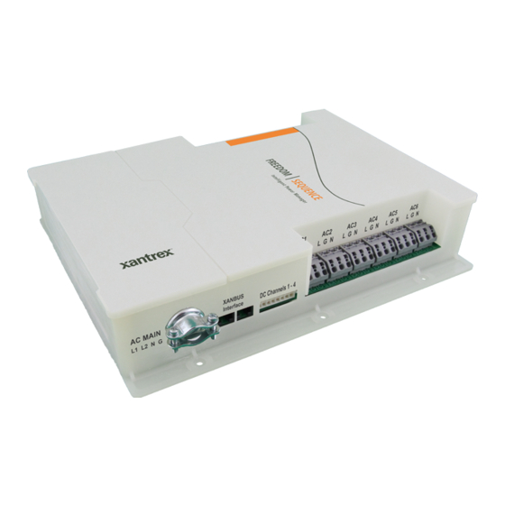
FSequence IPM Install Guide.book Page 5 Thursday, October 6, 2011 3:21 PM Features This section describes the different parts of the Freedom Sequence. Item Description AC Main section contains the current and voltage sensors to Ports and Terminals monitor the AC source and provides the pass-through wiring from a transfer switch to the vehicle’s main distribution panel. - Page 16 AC 2 AC 1 DC RELAYS HOUSE START BATTERY AC LINE AC DISCONNECT TO SHORE DC LINE XANBUS DC DISCONNECT 300A CONNECTION Figure 3 Typical RV Wiring Diagram With Freedom Sequence (six-circuit model shown) Freedom Sequence Intelligent Power Manager Installation Guide...
- Page 17 FSequence IPM Install Guide.book Page 7 Thursday, October 6, 2011 3:21 PM Features Tools and Materials Location Install the power manager in a location that meets the following Tools requirements: 3.5mm blade long neck screwdriver for opening Condition Requirement the AC relay cage clamp connectors The power manager must be installed in a dry location not subject to Phillips screwdriver for removing and replacing moisture especially rain, spray, or splashing bilge water.
- Page 18 FSequence IPM Install Guide.book Page 8 Thursday, October 6, 2011 3:21 PM Features Horizontally Flat Surface Figure 4 Mounting Orientations (Deck or Ceiling) Figure 5 Mounting Orientations (Wall) Freedom Sequence Intelligent Power Manager Installation Guide...
- Page 19 See notes below. excessive for the conductors and insulation. Failure to follow these instructions will result in death or serious In recognition of this exception, the Freedom Sequence allows you the injury. option to disable the Breaker Derating by changing the default Enabled to Disabled in the Advanced Settings screen.
- Page 20 N/O* Brown Common Blue N/C** Orange N/O* Brown Common Blue N/C** Orange N/O* Brown Common Blue N/C** * Normally Open ** Normally Closed Yellow B+ sense Brown Common Black NEG – POS + Freedom Sequence Intelligent Power Manager Installation Guide...
-
Page 21: Installing The Freedom Sequence
Configure Freedom Sequence via the SCP. Follow the requirements laid out under the section “Location” on page 7. To begin, (1) place the Freedom Sequence on the surface to which it will be Turn on the RV power system. installed and mark the mounting holes on the surface with a pencil. (2) Pilot drill the holes, if necessary. - Page 22 • All AC relay circuits must have a common disconnect and be connected to the RECEPTACLE same pole of the disconnect (i.e. Main AC Panel). MAIN AC Failure to follow these instructions can result in death or serious PANEL injury. Figure 6 Switch and Disconnect Locations Freedom Sequence Intelligent Power Manager Installation Guide...
- Page 23 FSequence IPM Install Guide.book Page 13 Thursday, October 6, 2011 3:21 PM Installing the Freedom Sequence Step 2: Connecting the AC Main wires 10mm AC Main wires MAIN AC PANEL Locate the two AC Main cable holes—one on each side of the power manager. Starting on one side, (1) Strip the phase and neutral wires of the AC Main cables as shown above.
- Page 24 3.5mm blade long neck screwdriver by inserting the tip (5) Tug the wires (soft-pull test) to make sure they are firmly in place. Correct any loosened through the square hole. connections. Freedom Sequence Intelligent Power Manager Installation Guide...
- Page 25 FSequence IPM Install Guide.book Page 15 Thursday, October 6, 2011 3:21 PM Installing the Freedom Sequence Step 4: Connecting the DC Relay wires DC device wire/s N/O* Orange L G N Common Brown N/C** Blue N/O* Orange Common Brown N/C**...
- Page 26 (1) Pick the Xanbus SCP as the first Xanbus component in the network. Plug the SCP’s left Xanbus display panel, make sure it is receiving power from the system. (3) Bring the Freedom Sequence to network port with a network terminator. (2) Using a CAT5 network cable, plug the SCP’s right Xanbus Safe Mode from the Config screen of the SCP.
- Page 27 Connect the RV to shore power. (1) Close the land-based AC Breaker; (2) the transfer switch breaker and; (3) all breakers in the main AC panel. Lastly, bring the Freedom Sequence out of Safe Mode from the Config screen of the SCP to Operating Mode. Refer to the Owner’s Guide for detailed instructions.
-
Page 28: Freedom Sequence Scp Menu Map
FSequence IPM Install Guide.book Page 18 Thursday, October 6, 2011 3:21 PM Freedom Sequence SCP Menu Map Freedom Sequence SCP Menu Map Freedom Sequence Intelligent Power Manager Installation Guide... -
Page 29: Specifications
FSequence IPM Install Guide.book Page 19 Thursday, October 6, 2011 3:21 PM Specifications NOTE: Specifications are subject to change without prior notice. Physical Specifications Electrical Specifications Dimensions: L×W×H 254×355.6×63.5 mm (10×14×2.5 in.) AC Main input voltage 120/240 VAC single/split phase Weight 1 kg (2.2 lbs) AC Main input current... - Page 30 FSequence IPM Install Guide.book Page 20 Thursday, October 6, 2011 3:21 PM...
- Page 31 FSequence IPM Install Guide.book Page i Thursday, October 6, 2011 3:21 PM...
- Page 32 FSequence IPM Install Guide.book Page ii Thursday, October 6, 2011 3:21 PM Xantrex Technology USA Inc. 1 800 670 0707 Tel 1 800 994 7828 Fax www.xantrex.com Printed in China. 975-0594-01-01...
Need help?
Do you have a question about the Freedom Sequence and is the answer not in the manual?
Questions and answers