Sign In
Upload
Download
Table of Contents
Contents
Add to my manuals
Delete from my manuals
Share
URL of this page:
HTML Link:
Bookmark this page
Add
Manual will be automatically added to "My Manuals"
Print this page
×
Bookmark added
×
Added to my manuals
Manuals
Brands
Valeo Manuals
Air Compressor
TM55
Service manual
Valeo TM55 Service Manual
Hide thumbs
1
2
3
Table Of Contents
4
5
6
7
8
9
10
11
12
13
14
15
16
17
18
19
20
21
22
23
24
25
26
27
28
29
30
31
32
33
34
35
36
37
38
39
40
41
42
43
44
45
46
47
48
49
50
51
page
of
51
Go
/
51
Contents
Table of Contents
Troubleshooting
Bookmarks
Table of Contents
Table of Contents
1 Product Description
Compressor Speed (Rpm)
Conversion Factors
2 Operation Precautions
3 Handling Instructions
Maintenance Precautions
Work Area
Refrigerant Handling
Compressor Handling
Compressor Removal
Oil Return Operation
Oil Handling
Oil Level at Inclination Conditions
Front Lifting
Lateral Inclination
Oil Contamination
Oil Check
Replacement of Components
Leak Test
Refrigerant Charging
Storing a Repaired Compressor
4 Troubleshooting
Compressor Troubleshooting
Compressor Troubleshooting Tree
A/C Cycle Diagnosis by Gauge Pressure
5 Tightening Torques
6 Service Procedures - Magnetic Clutch
7 Service Procedures - Shaft Seal Assembly
8 Service Tools
9 Service Parts
Advertisement
Quick Links
1
1- Product Description
2
Compressor Handling
3
Oil Return Operation
4
Oil Check
5
Replacement of Components
6
6- Service Procedures - Magnetic Clutch
7
9- Service Parts
Download this manual
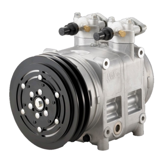
SERVICE MANUAL
Valeo TM55 & TM65 Compressors
Copyright © 2019 Valeo Japan CO., LTD. | All Rights Reserved.
Table of
Contents
Previous
Page
Next
Page
1
2
3
4
5
Advertisement
Table of Contents
Need help?
Do you have a question about the TM55 and is the answer not in the manual?
Ask a question
Questions and answers
Related Manuals for Valeo TM55
Air Compressor Valeo TM08 Service Manual
(56 pages)
Air Compressor Valeo TM13 Service Manual
(56 pages)
Air Compressor Valeo TM15 Service Manual
(56 pages)
Air Compressor Valeo TM16 Service Manual
(56 pages)
Air Compressor Valeo TM65 Service Manual
(51 pages)
This manual is also suitable for:
Tm65
Table of Contents
Save PDF
Print
Rename the bookmark
Delete bookmark?
Delete from my manuals?
Login
Sign In
OR
Sign in with Facebook
Sign in with Google
Upload manual
Upload from disk
Upload from URL


Need help?
Do you have a question about the TM55 and is the answer not in the manual?
Questions and answers