Advertisement
Quick Links
TP1 Gebrauchsanleitung
TP1 Manual
1
Allgemeine Beschreibung
2
Sicherheitshinweise
2.1 Bestimmungsgemäße Verwendung
2.2 Installation & Inbetriebnahme
2.3 Anschlüsse prüfen
2.4 Einschalten des Systems
2.5 Messwerte prüfen
2.6 Funktionsfähigkeit prüfen
2.7 Funktionsstörung
3
Elektrische Daten
4
Montagehinweis
5
Anschlüsse
6
Einbau und Installation
6.1 Wegaufnehmer
6.2 Positionsgeber
6.2.1 Z-TP1-P06
6.2.2 Z-TP1-P07
6.2.3 Z-TP1-P08
7
Elektrischer Anschluss
7.1 Code 101/103
7.2 Code 102
7.3 Code 201/203/205
7.4 Steckerbelegung
8
Ausgangssignale
8.1 Impuls-Schnittstelle
8.2 SSI-Schnittstelle
8.3 DyMoS-Schnittstelle
8.4 Quadratur Schnittstelle
8.5 Analoge Schnittstellen
8.6 6-pol. Flanschstecker
9
Spezifische Stecker auf Anfrage
9.1 6-pol. Flanschstecker
9.2 12-pol. Flanschstecker
9.3 5-pol. Flanschstecker
10
Teach-In Funktion
11
Versatz des Positionsgebers
11.1 Fehlermeldung Positionsgeber
12
Notwendiges Zubehör
13
Optionales Zubehör
14
Bestellcode
Artikelnummer / Item number: 518885/03
1
2
2
2
2
2.1 Intended conditions of use
2
2.2 Installation & startup
2.3 Check connections
2
2
2.4 Turning on the system
2
2.5 Check measured values
2.6 Check functionality
2
2
2.7 Failure malfunction
3
3
4
3
5
3
6
4
4
6.1 Transducer
5
6.2 Position marker
6.2.1 Z-TP1-P06
5
5
6.2.2 Z-TP1-P07
5
6.2.3 Z-TP1-P08
7
6
6
7.1 Code 101/103
6
7.2 Code 102
7.3 Code 201/203/205
6
7
7.4 Pin configuration
8
8
8
8.1 Pulse interface
8
8.2 SSI interface
8.3 DyMoS interface
8
9
8.4 Quadratur interface
10
8.5 Analog output
8.6 6-pin flange connector
11
9
11
11
9.1 6-pin flange connector
9.2 12-pin flange connector
11
11
9.3 5-pin flange connector
10
12
11
13
13
11.1 Error conditions position marker
12
14
13
14
14
14
Änderungen vorbehalten / Subject to change without notice
General description
Safety instructions
Electrical data
Instruction for installation
Wiring
Mounting and installation
Electrical connection
Output signals
Special connectors on request
Teach-In function
Displacement of the position marker
Required accessories
Optional accessories
Ordering code
2
2
2
2
2
2
2
2
2
3
3
3
4
4
5
5
5
5
6
6
6
6
7
8
8
8
8
9
10
11
11
11
11
11
12
13
13
14
14
14
2012/11
Seite / page 1
Advertisement

Subscribe to Our Youtube Channel
Related Manuals for Siedle Novotechnik TP1 Series


Summary of Contents for Siedle Novotechnik TP1 Series
- Page 1 TP1 Gebrauchsanleitung TP1 Manual General description Allgemeine Beschreibung Sicherheitshinweise Safety instructions 2.1 Bestimmungsgemäße Verwendung 2.1 Intended conditions of use 2.2 Installation & Inbetriebnahme 2.2 Installation & startup 2.3 Check connections 2.3 Anschlüsse prüfen 2.4 Einschalten des Systems 2.4 Turning on the system 2.5 Messwerte prüfen 2.5 Check measured values 2.6 Check functionality...
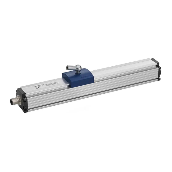
- Page 2 TP1 Gebrauchsanleitung TP1 Manual Allgemeine Beschreibung General description Die Baureihe TP1 ist ein magnetostriktiver Wegaufnehmer The TP1 series is a magnetostricitve transducer for direct, für die direkte, genaue und absolute Messung von Wegen accurate measurement of travel in display- or feedback applications.
- Page 3 TP1 Gebrauchsanleitung TP1 Manual Elektrische Daten / Electrical data Versorgungsspannung / Supply voltage: 24 VDC (siehe auch Datenblatt / see also data sheet) Stromaufnahme / Current draw: ≤ 100 mA typisch / typical Montagehinweis Instruction for installation Bei der Montage der Befestigungsklammern ist das The maximum torque of 200Ncm is to be considered by maximale Drehmoment von 200Ncm zu beachten.
- Page 4 TP1 Gebrauchsanleitung TP1 Manual Einbau / Installation 6.1 Wegaufnehmer / Transducer Im Lieferumfang enthalten: Spannklammern Z-46 inkl. Zylinderschrauben M5x20 Included in delivery: mounting clamps Z-46 incl. head cap screws M5x20 Beispiel Teileschlüssel / example ordering code: TP1-____-101-___-___ Markierung / Elektrischer Nullpunkt mark / electrical zero point Zubehör: Positionsgeber / Markierung / Elektrischer Nullpunkt...
- Page 5 TP1 Gebrauchsanleitung TP1 Manual 6.2 Positionsgeber / Position marker 6.2.1 Z-TP1-P06 (005693) 6.2.2 Z-TP1-P07 (005694) 6.2.3 Z-TP1-P08 (005695) Drehung des Positionsgebers führt zu einem Offset von 26,6mm. Rotation of the position marker result in an offset of 26,6 mm. Artikelnummer / Item number: 518885/03 Änderungen vorbehalten / Subject to change without notice 2012/11 Seite / page 5...
- Page 6 TP1 Gebrauchsanleitung TP1 Manual Elektrischer Anschluss / Electrical connection 7.1 TP1-____-___-___-101 TP1-____-___-___-103 7.2 TP1-____-___-___-102 7.3 TP1-____-___-___-201 TP1-____-___-___-203 TP1-____-___-___-205 Standard Kabel Standard cable Artikelnummer / Item number: 518885/03 Änderungen vorbehalten / Subject to change without notice 2012/11 Seite / page 6...
- Page 7 TP1 Gebrauchsanleitung TP1 Manual 7.4 Steckerbelegung / Pin configuration (Sicht auf den Flanschstecker / front view to the flange connector) 8-pol. Flanschstecker / 8-pin flange connector IEC 130-9, DIN 45326 Beispiel Teileschlüssel / example ordering code: TP1-____-___-___-101 Zubehör / accessories : Kupplungsdose / straight connector EEM 33-84;...
- Page 8 TP1 Gebrauchsanleitung TP1 Manual Ausgangssignale / Output Signals 8.1 Impuls-Schnittstelle / Pulse interface Beispiel Teileschlüssel: TP1-____-___-1__-___ Dose m. Kabel / Stecker / Plug Kabel / cable Signal Example ordering code : TP1-____-___-1__-___ connector w. cable 101, 102 201, 203, 205 Impuls / pulse EEM33-86, EEM33-87 PIN 1...
- Page 9 TP1 Gebrauchsanleitung TP1 Manual 8.4 Quadratur Schnittstelle / Quadrature interface Beispiel Teileschlüssel: TP1-____-___-8__-___ Example ordering code : TP1-____-___-8__-___ Dose m. Kabel / Stecker / Plug Kabel / cable Signal connector w. cable 201, 203, 205 Quadrature EEM33-86, EEM33-87 PIN 1 YE gelb / yellow WH weiss / white PIN 2...
- Page 10 TP1 Gebrauchsanleitung TP1 Manual 8.5 Analoge Schnittstellen / Analog Output Beispiel Teileschlüssel: TP1-____-___-41_-___ Example ordering code TP1-____-___-41_-___ Dose m. Kabel / Stecker / Plug Kabel / cable Signal connector w. cable 101, 102 201, 203, 205 Spannung / voltage EEM33-86, EEM33-87 nicht anschließen / PIN 1 YE gelb / yellow...
- Page 11 TP1 Gebrauchsanleitung TP1 Manual 6-pol. Flanschstecker / 6-pin flange connector IEC130-9, DIN 45326 Beispiel Teileschlüssel: TP1-____-___-___-103 Example ordering code : TP1-____-___-___-103 Stecker / Plug Signal Signal Signal Signal 0...10 VDC 0(4)...20 mA Start/Stop PIN 1 0…10 VDC 0(4)...20 mA - DATA - Start/Stop PIN 2 Signal GND...
- Page 12 TP1 Gebrauchsanleitung TP1 Manual Teach-In Funktion für analoge Varianten Teach-In function for analog models Teach-In nicht während des Maschinenbetriebes Do not activate Teach-In during machine operation. durchführen. Machine must be put out of operation before Die Anlage ist vorher außer Betrieb zu nehmen. activating Teach-In.
- Page 13 TP1 Gebrauchsanleitung TP1 Manual Ausgang / output DIAG V/mA 100% PROG 100% Messweg / stroke Bild / figure 1: Null- und/oder Endpunkt einstellen (z.B. 5...45 mm anstatt 0...50 mm). Setting up zero- and/or limit point (e.g. 5...45 mm instead of 0...50 mm). Versatz des Positionsgebers Displacement of the position marker Höhenversatz/...
- Page 14 TP1 Gebrauchsanleitung TP1 Manual Notwendiges Zubehör Required Accessories • Positionsgeber Z-TP1-P06 (Art.Nr. 005693) • Position marker Z-TP1-P06 (P/N 005693) • Positionsgeber Z-TP1-P07 (Art.Nr. 005694) • Position marker Z-TP1-P07 (P/N 005694) • Geführter Positionsgeber Z-TP1-P08 (Art.Nr. 005695) • Guided position marker Z-TP1-P08 (P/N 005695) Optionales Zubehör Optional accessories •...
Need help?
Do you have a question about the Novotechnik TP1 Series and is the answer not in the manual?
Questions and answers