Table of Contents
Advertisement
Quick Links
Advertisement
Table of Contents

Related Manuals for SawStop TSA-SA70


Summary of Contents for SawStop TSA-SA70
- Page 1 LARGE SLIDING TABLE OWNER’S MANUAL MODEL TSA-SA70...
- Page 2 The saw shown on the front cover is the Industrial Cabinet Saw, Model ICS. Your saw may look different. SawStop, the SawStop blade logo, and the configuration of this product are either registered trademarks or trademarks of SawStop, LLC. Software copyright by...
- Page 3 TO OUR CUSTOMERS Thank you for purchasing the SawStop Large Sliding Table. We are confident you will be pleased with its quality and performance. This manual tells you more about your large sliding table and how to operate and maintain it.
- Page 4 HOW TO GET HELP Missing Parts? Have Questions? Our technical support team is standing by M-F, 7am-5pm PST to help with whatever you need. Give us a call at 503.582.9934 Email us at SERVICE@SAWSTOP.COM...
-
Page 5: Table Of Contents
TABLE OF CONTENTS Product Specs................. Parts Inventory................. Parts & Hardware Lists..................... Tools Needed......................Getting to Know Your Large Sliding Table........Components......................Mounting Options..................... Front Mounting WITHOUT Left Wing............Center Mounting WITHOUT Left Wing............Rear Mounting WITHOUT Left Wing............. Front Mounting WITH Left Wing..............Center Mounting WITH Left Wing.............. - Page 6 TABLE OF CONTENTS Installing the Guide Bearing Assembly..............Setting the Bearing Tension..................Installing the Angle Guide Rail................. Installing the Crosscut Fence Assembly..............Crosscut Fence Assembly Configurations............... Euro Configuration..................Storage......................Installing the Logo Plate................... Adjustments..................Leveling........................Installing the Remaining Support Leg..............Aligning to the Blade....................
-
Page 7: Product Specs
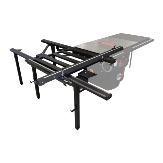
PRODUCT SPECIFICATIONS The SawStop Large Sliding Table is engineered for the demands of the Industrial woodshop and ensures precise, repeatable operation. This Sliding Table makes cutting sheet goods and larger stock easy, with maximum control and sure measurement. A rigid steel frame and 14 sealed, steel bearings ensure a reliable, smooth glide, and adjustability affords both traditional and Euro configurations for a max crosscut of 70”. -
Page 8: Parts Inventory
Certain components may have been pre-installed for shipping purposes. Parts Box (Labeled 2 of 2) Inner Guide Tube (Qty. 1) Outer Guide Tube (Qty. 1) Crosscut Fence (Qty. 1) Angle Guide Rail (Qty. 1) Mounting Bracket (Qty. 1) TSA-SA70 OWNER’S MANUAL... - Page 9 Flip Stop (Qty. 1) Positioning Plate (Qty. 1) Fence Lock Assembly (Qty. 1) Front Bracket (Qty. 1) Fence Extension (Qty. 1) Support Tube (Qty. 1) Logo Plate (Qty. 1) Lateral Bracket (Qty. 3) Sliding Table (Qty. 1) TSA-SA70 OWNER’S MANUAL...
- Page 10 M8 x 1.25 x 16 Hex Head Bolt (Qty. 14) 1.41 M5 x 0.8 x 20 Hex Head Bolt (Qty. 3) 1.40 M5 x 16 x 1 Washer (Qty. 3) 1.43 M5 Lock Nut (Qty. 3) M8 x 16 x 2 Washer (Qty. 8) TSA-SA70 OWNER’S MANUAL...
- Page 11 M4 x 0.7 x 12 Button Head Phillips Screw (Qty. 2) 2.11 M4 x 10 x 1 Washer (Qty. 2) Spacer (Qty. 2) M6 x 1.0 x 20 Lock Handle (Qty. 2) 2.11 M6 x 1.0 x 25 Thumb Screw (Qty. 2) TSA-SA70 OWNER’S MANUAL...
-
Page 12: Tools Needed
Metal cutting band saw or hacksaw with metal Drill • cutting blade 10mm wrench • • Rip fence or straight edge at least 30” long 10mm socket • • Level 5mm hex wrench • • Square 8mm wrench • Tape measure or calipers TSA-SA70 OWNER’S MANUAL... -
Page 13: Getting To Know Your Large Sliding Table
Angle Guide Rail Mounting Bracket Table Position Handle Positioning Plate Fence Pivot Plate Inner Guide Tube Crosscut Fence Bearing Guide Channel Fence Pivot Assembly Front Bracket Fence Lock Assembly Frame Support Bracket Fence Extension Support Tube Flip Stop TSA-SA70 OWNER’S MANUAL... -
Page 14: Mounting Options
Mounting Options The SawStop Large Sliding Table can be mounted to your SawStop table saw in any of six different table orientations and three fence positions. Fence Positions: 90° Euro: 90° Traditional: 45° Traditional: Provides the Large Positions the fence at Use traditional Sliding Table’s... -
Page 15: Center Mounting Without Left Wing
The ripping length with the crosscut fence in the traditional configuration is reduced from 49” to 37.5”. 45° Traditional Mounts Center of 90° Traditional Saw Cabinet TSA-SA70 OWNER’S MANUAL... -
Page 16: Front Mounting With Left Wing
45° Traditional Mounts Forward of Saw Cabinet 90° Traditional TSA-SA70 OWNER’S MANUAL... -
Page 17: Rear Mounting With Left Wing
Euro configuration while also maintaining the Mounts additional support to the left Rear of of the blade provided by the Saw Cabinet left extension wing. 45° Traditional 90° Traditional TSA-SA70 OWNER’S MANUAL... -
Page 18: Modifying Your Table Saw
Some of the steps below involve removing/installing your rails, switchbox, and extension wing. For those steps, please refer to your table saw manual and fence manual. (You can download copies of your manuals at www.sawstop.com.) DISCONNECT YOUR TABLE SAW FROM ELECTRICAL POWER BEFORE BEGINNING ANY MODIFICATIONS. -
Page 19: Installing Your Large Sliding Table
USING OTHER TYPES OF SAWS (SUCH AS A CIRCULAR SAW) CAN GENERATE ENOUGH HEAT TO BLISTER THE POWDER COATING. IT IS STRONGLY SUGGESTED THAT YOU USE A METAL CUTTING BAND SAW OR A HACK SAW WITH A METAL CUTTING BLADE ONLY. TSA-SA70 OWNER’S MANUAL... - Page 20 If necessary, complete the assembly of your saw then re-install the front and rear rails and the main tube (refer to your saw and fence manuals). When finished, continue to page 17. ⁄ ” TSA-SA70 OWNER’S MANUAL...
-
Page 21: Shortening The Rails Without The Extension Wing
USING OTHER TYPES OF SAWS (SUCH AS A CIRCULAR SAW) CAN GENERATE ENOUGH HEAT TO BLISTER THE POWDER COATING. IT IS STRONGLY SUGGESTED THAT YOU USE A METAL CUTTING BAND SAW OR A HACK SAW WITH A METAL CUTTING BLADE ONLY. TSA-SA70 OWNER’S MANUAL... - Page 22 PCS. Next, re-install the front and rear rails and the main tube (refer to your fence manual). When finished, continue on to the next page. TSA-SA70 OWNER’S MANUAL...
-
Page 23: Assembling The Support Legs
With the holes aligned, insert a hex head bolt (1.11) through a washer (1.10), then through one of the two 1.11 exposed holes in the leg bracket 1.10 and support leg (F). Secure the bolt using a 13mm wrench. TSA-SA70 OWNER’S MANUAL... - Page 24 Repeat step 6 to install the other crosscut fence storage bracket (1.16) to the remaining support with stepped leg bracket (H). Make sure the fence storage brackets (1.16) face away from the stepped portion of the stepped leg 1.16 brackets. TSA-SA70 OWNER’S MANUAL...
-
Page 25: Attaching The Mounting Bracket
Secure the bolt in place with a second washer (1.7) and a lock nut (1.39). Only finger tighten the nut at 1.39 EXTENSION WING this time. UNDER TABLE VIEW TSA-SA70 OWNER’S MANUAL... - Page 26 Check to make sure the mounting bracket is somewhat level, then use 13mm wrenches to tighten the bolts. Place one wrench on the bolt head to hold it in place and use the other wrench to tighten the nut. TSA-SA70 OWNER’S MANUAL...
- Page 27 1/16” below the top surface of the table, use the original wing hardware to attach the mounting bracket. Insert the bolt through the lock washer, through the mounting bracket and into the table. Only finger tighten the bolt at this time. TSA-SA70 OWNER’S MANUAL...
- Page 28 For PCS saws ONLY: Repeat step 3 for the other three sets of exposed holes. Check to make sure the mounting bracket is somewhat level, then use a 13mm wrench to tighten the bolts. TSA-SA70 OWNER’S MANUAL...
-
Page 29: Attaching The Positioning Plate
(E), then thread four socket head cap screws (1.36) 1.36 with four washers (1.10) through the sliding table positioning plate 1.10 into the exposed mounting holes in the sliding table mounting bracket. TSA-SA70 OWNER’S MANUAL... - Page 30 WITH WITHOUT EXTENSION WING Tighten the four socket head cap screws (1.36) with a 6mm hex wrench. 1.36 TSA-SA70 OWNER’S MANUAL...
-
Page 31: Attaching The Inner Guide Tube
Place the inner guide tube its rear edge (so the bearing guide channel faces up), and align the BEARING two round mounting holes in the GUIDE leg bracket with the two rear CHANNEL threaded holes in the inner guide tube (A). TSA-SA70 OWNER’S MANUAL... - Page 32 1.10 inner guide tube (A). Only finger tighten the bolt. 1.11 Repeat step 4 for the other three exposed holes in the positioning plate and inner guide tube (A). TSA-SA70 OWNER’S MANUAL...
- Page 33 Mount the front guide bearing bracket to the underside of the front of the inner guide tube using two hex head bolts (1.11) and two washers 1.10 (1.10). Use a 13mm wrench to tighten the bolts. 1.11 TSA-SA70 OWNER’S MANUAL...
- Page 34 (1.41) through three washers (1.40), then through the exposed holes in the mounting bracket and switchbox assembly, and securing the bolts with three lock nuts (1.43). Use an 8mm wrench to tighten the bolts. TSA-SA70 OWNER’S MANUAL...
-
Page 35: Installing The Sliding Table Support Assembly
1.44 1.50 bracket (1.50) and support tube (K), 1.10 and then through a second washer and a lock nut (1.39). Do not (1.10) fully tighten the lock nut at 1.10 this time. 1.39 TSA-SA70 OWNER’S MANUAL... - Page 36 Position the mounting bracket only within the area shown: a 6.5” x 4.5” area under the rear rail in the upper-right corner of the saw cabinet. Ensure the support tube (K) is level before attaching the mounting bracket (1.47). TSA-SA70 OWNER’S MANUAL...
- Page 37 Use a 13mm wrench to tighten the LOCK NUT two hex head bolts (1.44) in the support tube (K). Do not tighten the lock nut shown with the gray callout in the figure to the right at this time. 1.44 1.44 TSA-SA70 OWNER’S MANUAL...
-
Page 38: Installing The Lateral Brackets
(L), then through a washer (1.7) and a hex cap nut (1.8). Repeat this procedure for the other exposed hole in the leg bracket and lateral bracket. Tighten the nuts using a 13mm wrench. TSA-SA70 OWNER’S MANUAL... - Page 39 Position the remaining two lateral brackets underneath the positioning plate (I). Align the square mounting holes in the lateral brackets with the square holes in the positioning plate (I). Repeat step 2 to secure each lateral bracket in place. TSA-SA70 OWNER’S MANUAL...
-
Page 40: Installing The Support Legs
1.14 leg (F). Align the square mounting holes in the lateral bracket with the square holes in the stepped leg bracket (H), keeping the edge of the bracket generally parallel with the saw table. TSA-SA70 OWNER’S MANUAL... - Page 41 (1.6) through one of the exposed mounting holes in the stepped leg bracket lateral bracket (L), then through a washer (1.7) and hex cap nut (1.8). VIEW FROM UNDER STEPPED LEG MOUNTING BRACKET Repeat step 4. TSA-SA70 OWNER’S MANUAL...
- Page 42 The last support leg with the leg bracket will be installed after adjustments are made to the guide tubes. Check that the lateral brackets still level, then use a 13mm wrench to tighten the hex nuts (1.13) on both leveling feet (1.14). 1.13 1.14 TSA-SA70 OWNER’S MANUAL...
-
Page 43: Installing The Outer Guide Tube
(B). Repeat step 2 for the other exposed hole in the stepped leg bracket and outer guide tube (B). Move to the other stepped leg bracket and repeat the process. Tighten the bolts using a 13mm wrench. TSA-SA70 OWNER’S MANUAL... -
Page 44: Installing The Sliding Table & Sliding Table Stops
(1.2), then into one of the two holes on the inside edge of the outer guide tube (B). Secure the screw using a phillips head screwdriver. Repeat this process for the hole on the other end of the outer guide tube (B). TSA-SA70 OWNER’S MANUAL... -
Page 45: Adjusting The Sliding Table
(B). DO NOT OVERLOAD THE BEARINGS. OVERLOADING WILL CAUSE WARPING AND PREVENT THE SLIDING TABLE FROM MOVING SMOOTHLY. TSA-SA70 OWNER’S MANUAL... - Page 46 Slide the sliding table towards the rear of the guide tubes. Repeat steps 2-4 for the ball bearing at the rear, left side of the sliding table. TSA-SA70 OWNER’S MANUAL...
-
Page 47: Adjusting The Table Lock Handle
DO NOT OVER-TIGHTEN THE TABLE LOCK HANDLE AGAINST THE OUTER GUIDE TUBE. Use a 3/4” socket wrench or combination wrench to hold the eccentric nut still, and use a 10mm wrench to tighten the hex head bolt holding the table lock handle. TSA-SA70 OWNER’S MANUAL... -
Page 48: Adjusting The Spacing
Push against the outer edge of the table until it presses against the material from step 2. This will also cause the rail and bolts to move relative to the slotted holes in the stepped leg mounting brackets (h). TSA-SA70 OWNER’S MANUAL... - Page 49 (1.37) attaching the outer guide tube the stepped leg brackets (H). Remove the material from step 2. Recheck the spacing between the sliding table and the inner guide tube bearing channel make any further adjustments as necessary. TSA-SA70 OWNER’S MANUAL...
-
Page 50: Installing The Guide Bearing Assembly
(M), so the ball bearing extends under the outer guide tube (B). With the mounting holes aligned, insert the hex head bolt up through the exposed holes in the guide bearing assembly and sliding table. TSA-SA70 OWNER’S MANUAL... - Page 51 (B). Then re-tighten the lock nut. TSA-SA70 OWNER’S MANUAL...
- Page 52 If a lot of pressure is required, or it is not possible to stop the ball bearing from spinning, it is too tight and needs to be loosened. Repeat steps 1-7 for the other guide bearing assembly and mounting hole in the sliding table. TSA-SA70 OWNER’S MANUAL...
-
Page 53: Setting The Bearing Tension
The fifth, and furthest back, bearing is adjustable to prevent vertical movement of the rear of the sliding table. (See the exploded view on page 94 for reference). The two non-adjustable bearings are each partially covered by a guide channel scraper. TSA-SA70 OWNER’S MANUAL... - Page 54 If the sliding table “jumps” or does not travel smoothly when the front or rear bearings exit or enter the bearing guide channel, adjust the tension on the middle bearing. TSA-SA70 OWNER’S MANUAL...
- Page 55 Use a 10mm wrench to loosen the lock nut securing the ball bearing supported by the front bracket and slide the bearing up or down in the slotted hole in the bracket until the bearing contacts the underside of the sliding table (M). TSA-SA70 OWNER’S MANUAL...
- Page 56 If a lot of pressure is required, or it is not possible to stop the bearing from spinning, it is too tight and needs to be loosened. Use a 10mm wrench to re-tighten the lock nut. TSA-SA70 OWNER’S MANUAL...
-
Page 57: Installing The Angle Guide Rail
Slide the T-slot in the angle guide rail onto the two T-nuts until it is generally centered on the sliding table (M). Only finger tighten the bolts at this time. TSA-SA70 OWNER’S MANUAL... - Page 58 (front and back) to make sure they are still correct. Then tighten the two bolts. Thread a lock handle (2.11) into the smaller, threaded hole in a T-nut (2.10). 2.10 2.11 TSA-SA70 OWNER’S MANUAL...
- Page 59 (M). Use the ratchet capabilities of the lock handles to make sure the handles are generally horizontal so they do 2.11 not interfere with the travel of the sliding table. 2.11 TSA-SA70 OWNER’S MANUAL...
-
Page 60: Installing The Crosscut Fence Assembly
Align the T-nut in the fence pivot assembly with the right end of the T-slot on the face with two holes. If necessary, loosen the T-nut to provide clearance for the walls of the crosscut fence. TSA-SA70 OWNER’S MANUAL... - Page 61 Then re-tighten BLOCK the screw. Position the fence lock assembly next to the straight end of the MITER crosscut fence (the left end), with DETENT the miter detent knob in the position KNOB shown. TSA-SA70 OWNER’S MANUAL...
- Page 62 Slide the bottom of the fence pivot pin into the fence pivot plate at the FENCE front of the sliding table. Use the PIVOT PIN lock handle in the fence pivot plate to secure the fence pivot assembly (O). FENCE PIVOT PLATE TSA-SA70 OWNER’S MANUAL...
- Page 63 Your crosscut fence is now installed in the traditional configuration. TSA-SA70 OWNER’S MANUAL...
- Page 64 Do not over- tighten the thumb screws. TSA-SA70 OWNER’S MANUAL...
- Page 65 Slide the T-nut into the T-slot in the top of the crosscut fence (C). Tighten the lock handle to secure the flip stop in place on the crosscut fence. TSA-SA70 OWNER’S MANUAL...
-
Page 66: Crosscut Fence Assembly Configurations
(Q). Pivot the left end of the crosscut fence forward until the rounded T-nut slides out of the T-slot in the top of the angle guide rail (D). TSA-SA70 OWNER’S MANUAL... - Page 67 Slide the fence pivot assembly out of the right side of the T-slot in the crosscut fence (C). TSA-SA70 OWNER’S MANUAL...
- Page 68 Position the crosscut fence the rear of the sliding table (M), with the smooth face of the crosscut fence facing towards the front of the saw, and the beveled end of the crosscut fence extending away from the table saw. TSA-SA70 OWNER’S MANUAL...
- Page 69 T-nut aligns with the T-slot in the top of the angle guide rail (D). Slide the rounded T-nut into the T-slot in the top of the angle guide rail (D). TSA-SA70 OWNER’S MANUAL...
-
Page 70: Storage
In order to store your crosscut fence assembly, follow steps 1-3 and step 5 of the Euro Configuration instructions to remove the crosscut fence assembly from the sliding table, and set it in the crosscut fence storage brackets attached to the support legs shown below. TSA-SA70 OWNER’S MANUAL... -
Page 71: Installing The Logo Plate
(S), then through each of the holes in the stepped leg mounting bracket (H), followed by a washer (1.7) and a hex cap nut (1.8). Tighten the nuts using a 13mm wrench. TSA-SA70 OWNER’S MANUAL... -
Page 72: Adjustments
Lay a straight edge across the front of the sliding table top so that it extends over the top of the table saw near the front of the mounting bracket. TSA-SA70 OWNER’S MANUAL... - Page 73 Repeat step 2, but lay the straight edge across the sliding table top near the rear of the mounting bracket. TSA-SA70 OWNER’S MANUAL...
- Page 74 Use a 13mm wrench to tighten the four hex head bolts attaching the mounting bracket to the extension wing or saw table. For PCS with extension wing: Use 13mm wrenches to tighten the M8 bolts and M8 nuts. TSA-SA70 OWNER’S MANUAL...
-
Page 75: Installing The Remaining Support Leg
Attach the leg bracket to the outer guide tube using two hex head bolts (1.44) and two washers (1.10). (These bolts and washers are what were leftover from hardware bag 3). Use a 13mm wrench to tighten the bolts. TSA-SA70 OWNER’S MANUAL... - Page 76 WITHOUT EXTENSION WING Thread the leveling foot out of the support leg until the bottom of the leveling foot rests on the floor. Use a 13mm wrench to tighten the hex nut to secure the leveling foot. TSA-SA70 OWNER’S MANUAL...
-
Page 77: Aligning To The Blade
8-12” of clearance between the beveled end of the fence and the saw blade. Raise the saw blade to the highest elevation. Place a straightedge or rip fence flush against the left side of the blade. TSA-SA70 OWNER’S MANUAL... - Page 78 TSA-SA70 OWNER’S MANUAL...
- Page 79 Move the rear end of the outer guide tube slightly towards the blade. TSA-SA70 OWNER’S MANUAL...
- Page 80 It will be aligned later, so do not re-tighten the hex head bolt to secure it in place at this time. TSA-SA70 OWNER’S MANUAL...
-
Page 81: Setting The Miter Angle Ruler (Front)
Do not tighten the lock handle or the miter lock handle on the fence lock assembly. Use a machinist or engineering square to position the crosscut fence exactly 90 degrees relative to the saw blade. TSA-SA70 OWNER’S MANUAL... - Page 82 6. Re-tighten the hex head bolts to lock the angle guide rail in place. Tighten the lock handle and the miter lock handle on the fence lock assembly to lock the crosscut fence in place. TSA-SA70 OWNER’S MANUAL...
- Page 83 When aligning the fence with the desired marking on the miter angle ruler, read markings on the side of the fence that faces away from the operator. TSA-SA70 OWNER’S MANUAL...
-
Page 84: Setting The Miter Angle Ruler (Rear)
Use a machinist or engineering square to position the crosscut fence exactly 90 degrees relative to the saw blade. Tighten the lock handle and the miter lock handle on the fence lock assembly to lock the crosscut fence in place. TSA-SA70 OWNER’S MANUAL... - Page 85 Re- tighten the hex head bolt. TSA-SA70 OWNER’S MANUAL...
-
Page 86: Setting The Crosscut Fence Ruler
Make sure the table saw motor is off and the blade is completely stopped. Install the crosscut fence in the traditional configuration (at the front of the sliding table). Adjust the flip stop assembly to about 12” from the blade. TSA-SA70 OWNER’S MANUAL... - Page 87 Push the Start/Stop paddle in to stop the blade and power OFF the saw. Use a tape measure to check the dimension of the cut piece of wood. TSA-SA70 OWNER’S MANUAL...
- Page 88 TO REDUCE THE POTENTIAL FOR KICKBACK AND A SERIOUS INJURY, MOVE THE RIP FENCE OUT OF CONTACT WITH THE WORKPIECE WHEN CROSS-CUTTING TO PREVENT THE WORKPIECE FROM BINDING BETWEEN THE RIP FENCE AND THE BLADE. TSA-SA70 OWNER’S MANUAL...
-
Page 89: Operations
To prevent the sliding table from moving, push the table lock handle toward the back of the sliding table. When the sliding table is not in use, lock it in place so that it will not move unexpectedly. TSA-SA70 OWNER’S MANUAL... - Page 90 The sliding crosscut table assembly can then be lifted up and moved to the desired location. TSA-SA70 OWNER’S MANUAL...
-
Page 91: Reference
Large Sliding Table system is modified without the prior written permission of SawStop, LLC, or if the Large Sliding Table system is located or has been used outside of the country where the authorized SawStop distributor from whom the Large Sliding Table system was purchased resides. -
Page 92: Safety
Everyday eyeglasses are not safety glasses. 6. Keep hands out of the line of the saw blade. Never reach around or over the saw blade. Keep proper footing and balance at all times. TSA-SA70 OWNER’S MANUAL... - Page 93 Any parts that are damaged should be properly repaired or replaced. TSA-SA70 OWNER’S MANUAL...
-
Page 94: Support System Exploded View
Support System Exploded View TSA-SA70 OWNER’S MANUAL... -
Page 95: Support System Parts List
M6 x 1.0 Lock Nut TSA-SA70-032 1.33 Positioning Plate TSA-SA70-033 1.10 M8 x 19 x 2 Washer TSA-SA70-034 1.11 M8 x 1.25 x 16 Hex Head Bolt TSA-SA70-035 1.36 M8 x 1.25 x 12 Socket Head Cap Screw TSA-SA70-036 TSA-SA70 OWNER’S MANUAL... - Page 96 M5 x 1.25 x 18 Pan Head Phillips Self-Tapping Screw TSA-SA70-048 1.49 Sliding Table Support Sleeve TSA-SA70-049 1.50 Frame Support Mounting Bracket TSA-SA70-050 1.39 M8 x 1.25 Lock Nut TSA-SA70-051 1.52 M8 x 1.25 x 16 Carriage Head Shoulder 2.3mm Bolt TSA-SA70-052 1.53 Support Tube TSA-SA70-053 TSA-SA70 OWNER’S MANUAL...
- Page 97 This page is blank. TSA-SA70 OWNER’S MANUAL...
- Page 98 Table Assembly Exploded View TSA-SA70 OWNER’S MANUAL...
- Page 99 6mm Hex T-Wrench TSA-SA70-085 2.31 5mm Hex T-Wrench TSA-SA70-086 2.32 Table Lock Handle TSA-SA70-087 2.33 M10 x 14.5 Wave Washer TSA-SA70-088 2.34 M6 x 13 x 1 Washer TSA-SA70-089 2.35 Guide Bearing Bracket TSA-SA70-090 2.36 Guide Bearing Assembly TSA-SA70-091 TSA-SA70 OWNER’S MANUAL...
-
Page 100: Crosscut Fence Exploded View
Crosscut Fence Exploded View TSA-SA70 OWNER’S MANUAL... -
Page 101: Crosscut Fence Parts List
19.2 x 28 x 1.5 Plastic Washer (Adhesive Backed) TSA-SA70-123 2.10 M6 x 1.0 x 3.5 T-Nut TSA-SA70-124 3.23 Spring Pin (6mm x 20mm) TSA-SA70-125 3.35 Crosscut Fence Miter Lock Glide Pad TSA-SA70-126 3.36 Adhesive Miter Plate Glide Pad Tape TSA-SA70-127 TSA-SA70 OWNER’S MANUAL... - Page 102 Miter Detent Knob TSA-SA70-135 3.45 M6 x 1.0 Miter Lock Handle TSA-SA70-136 3.46 Crosscut Fence Miter Lock Pivot Sleeve TSA-SA70-137 3.47 19.2 x 28 x 1.5 Plastic Washer TSA-SA70-138 3.48 15mm O-Ring TSA-SA70-139 3.49 Miter Detent Pin Block TSA-SA70-140 TSA-SA70 OWNER’S MANUAL...
- Page 103 This page is blank. TSA-SA70 OWNER’S MANUAL...
- Page 104 SawStop, LLC 11555 SW Myslony St | Tualatin, Oregon 97062 USA www.sawstop.com Main Phone: (503) 570-3200 Service: (503) 582-9934 Fax: (503) 570-3303 Email: info@sawstop.com September 2017 - 1.1...
Need help?
Do you have a question about the TSA-SA70 and is the answer not in the manual?
Questions and answers