Advertisement
Quick Links
Advertisement

Related Manuals for SawStop MB-PCS-000


Summary of Contents for SawStop MB-PCS-000
- Page 1 SawStop ® Professional Cabinet Saw Mobile Base INSTALLATION GUIDE Model MB-PCS-000 Model MB-PCS-000...
-
Page 2: Warranty
SawStop will repair the mobile base, provided it is returned to SawStop, shipping prepaid, within the warranty period. This warranty is void if the mobile base is modified without the prior permission of SawStop, or if the mobile base is located or has been used outside of the country where the authorized SawStop distributor from whom the mobile base was purchased resides. - Page 3 Lock Nuts, Shoulder Socket Button Head Socket M6 (2) Extension Spring, (1) Screw, M8 x 17.7 (1) Bolts, M10 x 40 (2) Fixed Wheel Axles Model MB-PCS-000 Lock Washers, Washers, Hex Bolts, Washers, Flange Lock Caster Nuts, M10.5 x 17 (4) M10.5 x 20 (4)
-
Page 4: Start Here
If you are missing the hardware pack or any of the other mobile base components, call the SawStop Service Department at 503-582-9934 for replacements. - Page 5 Fig. 4. Make sure that the caster support is oriented so that the linkage bar is next to the front of the cabinet. linkage bar mounting shoulder down Fig. 4 SawStop Professional Cabinet Saw Mobile Base ®...
- Page 6 (see Fig. 6). Note that this bolt is different than the bolt used to secure the rear of the caster support to the cabinet. Fully tighten the bolt using a 5 mm hex key. Fig. 6 SawStop Professional Cabinet Saw Mobile Base ®...
- Page 7 Fig. 9. Insert the pedal assembly as far as possible and make sure that the foot pad is facing the top of the cabinet. Fig. 9 SawStop Professional Cabinet Saw Mobile Base ®...
- Page 8 Fig. 11 SawStop Professional Cabinet Saw Mobile Base ®...
- Page 9 Fig. 13a bar must be farther away from the saw than the pedal assembly wheel support Fig. 13b SawStop Professional Cabinet Saw Mobile Base ®...
- Page 10 M10.5 x 20 washers to mount the caster extension bar to the caster support arms (see Fig. 16). Fully tighten the bolts with a 6 mm hex key. Fig. 16 SawStop Professional Cabinet Saw Mobile Base ®...
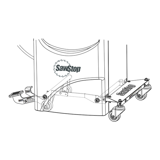
- Page 11 Fig. 17. Make sure that the plate SawStop logo faces up. Secure the support plate to the caster support arms with two M6 x 40 hex bolts, two M6 x 16 washers, and two M6 flange lock nuts.
- Page 12 Also, if you have an extension table with support legs attached to your saw, you will need to remove the support ® legs or rotate them out of the way. Steps 2 and 3 below describe how to rotate the support legs on a SawStop T-Glide Professional Series II extension table out of the way.
- Page 13 If you are missing the hardware pack or any of the other mobile base components, call the SawStop Service Department at 503-582-9934 for replacements.
- Page 14 Fig. 25. Make sure that the caster support is oriented so that the linkage bar is next to the front of the cabinet. front linkage bar Fig. 25 SawStop Professional Cabinet Saw Mobile Base ®...
- Page 15 Fully tighten the nut using a 17 mm wrench and a 10 mm wrench. end with a mounting shoulder support arms wheel support 3 inch wheel Fig. 28 SawStop Professional Cabinet Saw Mobile Base ®...
- Page 16 (see Fig. 31). There is a circular groove on the large pin to hold the spring in place. large pin small pin Fig. 31 SawStop Professional Cabinet Saw Mobile Base ®...
- Page 17 M8 x 20 button head socket bolt, one M8 x 13.6 lock washer, and one M8 x 18 washer (see Fig. 33). Fully tighten the bolt using a 5 mm hex key. Fig. 33 SawStop Professional Cabinet Saw Mobile Base ®...
- Page 18 Fig. 35). Note that this bolt is different than the bolt used to secure the rear of the wheel support to the cabinet. Fully tighten the bolt using a 5 mm hex key. Fig. 35 SawStop Professional Cabinet Saw Mobile Base ®...
- Page 19 M10.5 x 20 washers to mount the caster extension bar to the caster support arms (see Fig. 38). Fully tighten the bolts with a 6 mm hex key. caster extension bar Fig. 38 SawStop Professional Cabinet Saw Mobile Base ®...
- Page 20 21. Position the caster support plate on the top of the caster support arms so that the mounting holes align as shown in Fig. 39. Make sure that the SawStop logo faces up. Secure the support plate to the caster support arms with two M6 x 40 hex bolts, two M6 x 16 washers, and two M6 flange lock nuts.
- Page 21 Fig. 42 SawStop Professional Cabinet Saw Mobile Base ®...
- Page 22 SawStop Professional Cabinet Saw Mobile Base ®...
- Page 23 MB-PCS-022 Release Lever MB-PCS-023 Plastic Spacer (Adhesive Backed) MB-PCS-024 Caster Extension Tube MB-PCS-025 Caster Support Plate MB-PCS-026 3” Caster MB-PCS-027 SawStop Logo Label MB-PCS-028 Main Warning Label MB-PCS-029 Finger/Toe Warning Label MB-PCS-030 Raise Label MB-PCS-031 Lower Label MB-PCS-032 Owner’s Manual...
- Page 24 Tualatin, Oregon 97062 www.sawstop.com Main Phone - (503) 570-3200 Service - (503) 582-9934 Fax - (503) 570-3303 Email: info@sawstop.com Updates of this manual may be available at www.sawstop.com. © SawStop, LLC All Rights Reserved. M PCS 18 0011 00 January 2010...
Need help?
Do you have a question about the MB-PCS-000 and is the answer not in the manual?
Questions and answers