Table of Contents
Advertisement
Available languages
Available languages
Quick Links
10-512
Lees de volledige handleiding vóór installatie en ingebruikname.
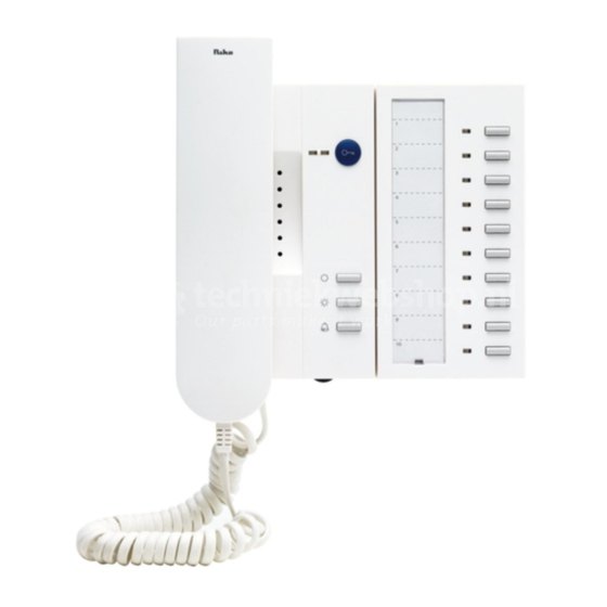
1. BESCHRIJVING
De 'Liberty Plus' telefoon (10-512) van het gamma Niko Access Control bestaat uit twee
modules, een basismodule (gelijk aan de 'Liberty Base') en een uitbreidingsmodule.
De basismodule is voorzien van 4 functietoetsen: 1 toets met deuropenerfunctie, 1 met
lichtschakelfunctie, 1 om de beltoon in/uit te schakelen en 1 toets met een vrije functie. U
kan het volume van de beltoon regelen met het instelwieltje onderaan de binnenpost. De
uitbreidingsmodule is voorzien van 10 vrije functietoetsen met naamplaat.
2. MoNtaGE
Controleer of de volgende componenten aanwezig zijn:
- telefoondoos met hoorn
Welke kabels zijn nodig?
Niko raadt het volgende aan:
- JYSTY(-F2) 3 x 2 x 0,8mm
- TVVF (-F2) 3 x 2 x 0,8mm
- TPVF 3 x 2 x 0,6mm (Beperkt het aantal aan te sluiten componenten. Voor specificaties,
zie technische catalogus Niko Access Control).
tip: Gebruik in één systeem voor alle producten van het gamma Niko Access Control dezelfde
kleurencode voor dezelfde klemmen (a, b, P...)!
opmerking: Niet alle voorziene paren van de kabel worden gebruikt. Als een paar beschadigd wordt
of u wenst over te stappen op videofonie, zijn er dus voldoende reserveparen aanwezig.
Montage binnenpost
De binnenpost bestaat uit één basis met
twee fronten: één voor de basismodule en
één voor de uitbreidingsmodule.
Maak beide fronten van de binnenpost los
van de basis op analoge wijze (fig.1).
1. Plaats een schroevendraaier van ±7mm
breed in de kleine opening in de basis
van de binnenpost. Oefen druk uit tot het
front loskomt.
2. Haak het front onderaan van de basis.
3. Haak het front bovenaan van de basis.
NL
fig.1: fronten van de binnenpost verwijderen
1
3
2
1
Advertisement
Table of Contents

Related Manuals for Niko 10-512


Summary of Contents for Niko 10-512
- Page 1 Lees de volledige handleiding vóór installatie en ingebruikname. 1. BESCHRIJVING De ‘Liberty Plus’ telefoon (10-512) van het gamma Niko Access Control bestaat uit twee modules, een basismodule (gelijk aan de ‘Liberty Base’) en een uitbreidingsmodule. De basismodule is voorzien van 4 functietoetsen: 1 toets met deuropenerfunctie, 1 met lichtschakelfunctie, 1 om de beltoon in/uit te schakelen en 1 toets met een vrije functie.
- Page 2 10-512 Voer de kabel in via de opening aan de achterkant van de binnenpost (fig.2). Monteer de basis van de binnenpost op de gewenste hoogte op de wand met behulp van de daarvoor voorziene montagegaten. Sluit drie draden van de kabel aan op klemmen a, b en P van de binnenpost.
- Page 3 10-512 Voorbeeld van een compleet aansluitschema Let op: Het is mogelijk enkel voeding 10-801 of 10-802 (3-draads) te gebruiken. In dat geval kan u echter max. 5 Liberty Plus binnenposten en 2 buitenposten aansluiten. Bij grotere systemen is het vereist 10-804 of 10-805 in combinatie met 10-801 of 10-802 te gebruiken.
- Page 4 10-512 3. WERKING, GEBRUIK EN PRoGRaMMERING fig.5: vooraanzicht van de binnenpost Als de installatie correct uitgevoerd is en op het net aangesloten wordt, licht de LED op de voedingsmodule (10-801 of 10-802) op. De LED aan de buitenpost licht eveneens op en verlicht de vandaalbestendige naamplaat.
- Page 5 10-512 LED-indicatie basismodule Betekenis De rode LED licht continu op. De beltoon is uitgeschakeld. De lijn is bezet. Haak terug in en probeer het later De rode LED knippert 3x in 6s. opnieuw - Er is een oproep. - Er is een spraakverbinding omdat de hoorn afge- De groene LED licht continu op haakt werd.
- Page 6 10-512 Dankzij deze functie ziet u ook van welke geprogrammeerde buitenpost een oproep afkomstig is. De rode indicatie-LED licht op. Druk op de bijhorende functietoets om het deuropenerrelais te schakelen. 2) Een interne oproep maken Druk op de functietoets om een geprogrammeerde binnenpost op te bellen. Zolang daar niet opgenomen wordt, knippert de indicatie-LED van de functietoets.
- Page 7 10-512 MoGELIJKE INStELLINGEN Beltoon op de binnenpost uitschakelen Druk op functietoets ‘3’. De rode LED licht op als de beltoon uitgeschakeld is. Volume van de beltoon wijzigen Gebruik het instelwieltje onderaan de binnenpost (fig.5) om het volume te wijzigen. Beltoon aan de binnenpost wijzigen Oproep via een buitenpost: Voor de Liberty binnenpost kan u kiezen uit 13 verschillende beltonen.
- Page 8 10-512 Interne oproep programmeren en beltoon wijzigen Interne oproep programmeren, zie ‘Programmeren zonder servicetoestel (10-870)’. Om de beltoon voor een interne oproep aan de binnenpost te wijzigen, drukt u 8s op functietoets 3 (van de basismodule). U hoort een bevestigingstoon. Druk op de blauwe deuropener- toets.
- Page 9 8 op de bus te zetten. Etagedeuropener-functie in-/uitschakelen Na een oproep via de etagebeldruk- knop opent de deuropenertoets de deur van het appartement gedu- rende 30s. Programmeer stuur- functie 11 op een Niko Access Control relais (10-830, 10-836 of 10-837) dat de appartementsdeur kan openen.
- Page 10 10-512 Haak de hoorn af van de bin- Een paralleloproep nenpost (=MASTER) waarmee inschakelen de andere binnenposten parallel moeten functioneren. Als een binnenpost rinkelt, zal elke parallel geprogrammeerde binnen- post ook rinkelen. Voer bovenstaande acties uit op de binnenpost(en) (= SLAVE) die parallel moet(en) functioneren.
- Page 11 10-512 De ingestelde programmering deblokkeren Let op! Activeer eerst de programmeermo- dus op de voeding. Voer vervolgens stappen 1 t.e.m. 4 uit. Beëindig ten slotte de programmeermodus op de voeding. terugkeren naar fabrieksinstellingen Druk de deuropenertoets gedurende 8s. in. Stap 4: Verlaat de programmeermodus van de binnenpost Druk functietoets 3 kort in om de programmeermodus van de binnenpost te verlaten.
- Page 12 10-512 De uitbreidingsmodule programmeren Stap1: Zet de binnenpost in programmeermodus Druk gedurende 8s op functietoets 3 van de basismodule tot u een korte Laat de functie- bevestigingstoon hoort en de eerste 7 LEDs van de uitbreidingsmodule knip- toets los peren.
- Page 13 10-512 oproepomleiding Druk kort op functie- Druk kort op de Druk op de geprogrammeer- toets 4. vrije functietoets de functietoets. De indicatie-LED De indicatie-LEDs knip- waaraan u de func- licht continu op. Een oproep van peren. tie wil toewijzen. een buitenpost wordt naar een De eerste 7 LED’s...
-
Page 14: Onderhoud Van Het Product
10-512 Stap 5: Verlaat de programmeermodus van de binnenpost Druk kort op functietoets 3 van de basismodule om de programmeermodus van de binnenpost te verlaten. De eerste 7 indicatie-LED’s doven. * Let op: Vooraleer u deze functie programmeert, dient u best eerst de buitenpost(en) -
Page 15: Technische Gegevens
- het feit dat een handleiding alleen algemene bepalingen vermeldt en dient gelezen te worden binnen het kader van elke specifieke installatie; - de regels van goed vakmanschap. - Bij twijfel kan u de supportdienst van Niko raadplegen of contact opnemen met een erkend controleorganisme. Support België: Support Nederland: tel. - Page 16 - De dwingende bepalingen van de nationale wetgevingen betreffende de verkoop van consumptiegoederen en de bescherming van de consumenten van de landen waarin Niko rechtstreeks of via zuster/dochtervennootschappen, filialen, distributeurs, agenten of vaste vertegenwoordigers verkoopt, hebben voorrang op bovenstaande bepalingen.
-
Page 17: Montage
Lisez entièrement le mode d’emploi avant toute installation et mise en service. 1. DESCRIPtIoN Le parlophone ‘Liberty Plus’ (10-512) de la gamme Niko Access Control comprend deux modules, un module de base (semblable au ‘Liberty Base’) et un module d’extension. - Page 18 10-512 Passez le câble à travers l’ouverture présente à l’arrière du poste intérieur (fig.2). Montez la base du poste intérieur sur un mur à la hauteur désirée à l’aide des trous de montage prévus à cet effet. Raccordez trois fils du câble aux bornes a, b et P du poste intérieur.
- Page 19 10-512 Exemple de schéma de raccordement complet attention: Il est possible de n’utiliser qu’une alimentation 10-801 ou 10-802 (à 3 fils). Dans ce cas, vous ne pourrez raccorder que max. 5 postes intérieurs Liberty Plus et 2 postes extérieurs. Pour des systèmes plus étendus, il faut utiliser une alimentation 10-804 ou 10-805 en combinaison avec une alimentation 10-801 ou 10-802.
- Page 20 10-512 3. FoNCtIoNNEMENt, UtILISatIoN Et PRoGRaMMatIoN fig.5: vue de face du poste intérieur Si l’installation a été correctement réalisée et a été raccordée au réseau, la LED s’allume sur le module d’alimentation (10-801 ou 10-802). La LED du poste extérieur s’allume également et éclaire la plaque nominative antivandalisme.
- Page 21 10-512 Indication donnée par la LED sur le Signification module de base La LED rouge s’allume en continu. La sonnerie est coupée. La LED rouge clignote 3x en 6s. La ligne est occupée. Raccrochez et essayez plus tard. - Il y a un appel.
- Page 22 10-512 Grâce à cette fonction, vous voyez également de quel poste extérieur programmé pro- vient un appel. La LED rouge d’indication s’allume. Appuyez sur la touche de fonction correspondante pour activer le relais d’ouvre-porte. 2. Effectuer un appel interne Appuyez sur la touche de fonction pour appeler un poste intérieur programmé. Tant que personne ne répond, la LED d’indication de la touche de fonction clignote.
- Page 23 10-512 REGLaGES PoSSIBLES Déconnexion de la tonalité sur le poste intérieur Appuyez sur la touche de fonction ‘3’. La LED rouge s’allume lorsque la sonnerie est coupée. Modification du volume de la tonalité Pour modifier le volume de la sonnerie, utilisez la molette située sur le dessous du poste intérieur (fig.5).
- Page 24 10-512 Programmation d’un appel interne et modification de la tonalité Pour la programmation d’un appel interne, reportez-vous à ‘Programmation sans appareil de service (10-870)’. Pour modifier la tonalité d’un appel interne sur un poste intérieur, appuyez pendant 8s. sur la touche de fonction 3 (du module de base). Vous entendez une tonalité...
- Page 25 Après un appel effectué grâce au bouton de sonnerie d’étage, la touche de l’ouvre-porte ouvre la porte de l’appartement pendant 30s. Programmez la fonction de commande 11 sur un relais Niko Access Control (10-830, 10-836 ou 10-837) qui peut ouvrir la porte de l’appartement.
- Page 26 10-512 Décrochez le combiné du poste intérieur (=MAITRE) avec lequel activer un appel en parallèle les autres postes intérieurs doivent fonctionner en parallèle. Lorsqu’un poste intérieur sonne, chaque poste intérieur programmé en parallèle sonnera également. Effectuez les étapes décrites ci- dessus sur le(s) poste(s) intérieur(s)
- Page 27 10-512 Bloquer la programmation effectuée La programmation ne peut plus être modifiée. Débloquer la programmation effectuée attention! Activez d’abord le mode de pro- grammation sur l’alimentation. Ef- fectuez ensuite les étapes 1 à 4. Enfin, mettez fin au mode de pro- grammation sur l’alimentation.
- Page 28 10-512 Programmation du module d’extension Etape 1: Placez le poste intérieur en mode de programmation Appuyez pendant 8s. sur la touche de fonction 3 du module de base jusqu’à ce Relâchez la touche que vous entendiez une courte tonalité de confirmation et que les 7 premières de fonction.
- Page 29 10-512 Appuyez brièvement sur la Appuyez brièvement Déviation d’appel touche de fonction 4. sur la touche de fonc- Appuyez sur la touche de fonction Les LED d’indication clig- tion libre à laquelle programmée. La LED d’indication notent. vous voulez attribu- Décrochez le...
-
Page 30: Entretien Du Produit
10-512 Etape 5: Quittez le mode de programmation du poste intérieur Appuyez brièvement sur la touche de fonction 3 du module de base pour quitter le mode de program- mation du poste intérieur. Les 7 premières LED d’indication s’éteignent. * attention: Avant de programmer cette fonction, il vaut mieux d’abord munir le(s) poste(s) extérieur(s) d’une adresse et le(s) bloquer au moyen de l’appareil de service... -
Page 31: Caracteristiques Techniques
- ce mode d’emploi qui doit être lu dans le cadre de toute installation spécifique; - les règles de l’art. - En cas de doute, vous pouvez appeler le service ‘support Niko’ ou vous adresser à un organisme de contrôle reconnu. - Page 32 - Les dispositions contraignantes des législations nationales ayant trait à la vente de biens de consommation et la protection des consommateurs des différents pays où Niko procède à la vente directe ou par entreprises interposées, filiales, distributeurs, agents ou représentants fixes, prévalent sur les dispositions susmentionnées.
-
Page 33: Installation
- TPVF 3 x 2 x 0,6mm (Limits the number of components to be connected. For specifications, see technical catalogue Niko Access Control). tip: Use the same color code for identical terminals (a, b, P…) for all the Niko Access Control products in one system! Note: Not all provided cable pairs are used. - Page 34 10-512 Insert the cable through the opening provided at the back of the internal unit (fig.2). Mount the base of the internal unit on a wall at the desired height, using the installation holes provided for this purpose. Connect three wires of the cable to terminals a, b and P of the internal unit.
- Page 35 10-512 Example of a complete wiring diagram Note: It is possible to only use power supply 10-801 or 10-802 (3-wire). In this case, you can max. connect 5 Liberty Plus internal units and 2 external units. As for larger systems, it is required to use 10-804 or 10-805 in combination with 10-801 or 10-802.
- Page 36 10-512 3. oPERatIoN, USE aND PRoGRaMMING fig.5: front view internal unit If the installation has been carried out correctly and is connected to the mains, the LED on the power supply module (10-801 or 10-802) lights. The LED on the external unit also lights, thereby illuminating the vandalproof name plate.
- Page 37 10-512 LED indication basic module Meaning The red LED lights continuously. The ring tone is switched off. The line is busy. Put the receiver down and try The red LED blinks 3x in 6s. again later. - There is a call.
- Page 38 10-512 comes. The red indication LED lights. Press the corresponding function key to switch the door open relay. 2. Making an internal call Press the function key to call a programmed internal unit. For as long the call is not answered at the internal unit, the indication LED of the function key blinks.
- Page 39 10-512 PoSSIBLE SEttINGS Switching off the ring tone on the internal unit Press function key ‘3’. The red LED lights if the ring tone is switched off. Modifying the volume of the ring tone Use the setting wheel at the bottom of the internal unit (fig.5) to modify the volume.
- Page 40 10-512 Programming an internal call and modifying the ring tone For how to program an internal call, see ‘Programming without service set (10-870)’. To modify the ring tone for an internal call at the internal unit, press function key 3 (of the basic module) for 8s.
- Page 41 After a call via the floor bell push button, the door opener key opens the apartment door for 30s. Pro- gram control function 11 on a Niko Access Control relay (10-830, 10-836 or 10-837) that can open the apartment door.
- Page 42 10-512 Pick up the receiver of the inter- nal unit (=MASTER) with which activating a parallel call the other internal units have to function in parallel. If an internal unit rings, every pa- rallelly programmed internal unit also rings. Carry out the actions described...
- Page 43 10-512 Deblocking the set program- ming Note! First enter the power supply mo- dule’s programming mode. Then carry out steps 1 up to and incl. 4. Then exit the power supply mo- dule’s programming mode. Return to default settings Press the door opener key for 8s.
- Page 44 10-512 Programming function Step2 **: Step3: Step4: short operating description carrying out a choice of function Briefly press the bus action free function key to which you wish to assign the func- tion. Selection internal unit and Briefly press Briefly press function...
- Page 45 10-512 Sending control function Briefly press function key Briefly press the (11…20) 5. The indication LEDs free function key Press the programmed function simultaneously blink. to which you wish key. Control function 11…20 is to assign the func- sent on the bus.
-
Page 46: Product Maintenance
10-512 Step 5: Exit the internal unit’s programming mode Briefly press function key 3 of the basic module to exit the internal unit’s programming mode. The first 7 indication LEDs go out. * Note: Before programming this function, first assign an external unit address to the... -
Page 47: Technical Data
In case of a defect, you can return your product to a registered Niko wholesaler, together with a clear description of your complaint (Conditions of use, stated defect…). 7. GUaRaNtEE PRoVISIoNS - Period of guarantee: 2 years from date of delivery. The delivery date is the invoice date of purchase of the product by the consumer. - Page 48 10-512 - Niko cannot be held liable for a defect or damage as a result of an incorrect installation, improper or careless use or wrong usage or transformation of the goods. - The compulsory regulations of the national legislation concerning the sales of consumer...
Need help?
Do you have a question about the 10-512 and is the answer not in the manual?
Questions and answers