Table of Contents
Advertisement
Quick Links
Contents
Safety ............................................................................................................ 2
Section 1-Introduction ................................................................................. 3
General ......................................................................................................... 3
Wiring ........................................................................................................ 5
Differential Pressure Unit (DPU) ............................................................... 5
Specifications ............................................................................................... 6
General...................................................................................................... 6
Nuclear Qualifications ............................................................................... 6
Application Specifications ......................................................................... 7
Storage Specifications .............................................................................. 7
Section 2-Installation ................................................................................... 9
Mounting/Piping/DPU Installation ................................................................. 9
Electrical Connection .................................................................................... 9
Switch Use .................................................................................................... 9
Startup ........................................................................................................ 10
Switch Wiring .............................................................................................. 10
Section 3-Maintenance and Calibration ....................................................11
Tools............................................................................................................ 12
Bezel/Lens Assembly or Cover Installation and Removal........................... 12
Pointer Installation and Removal ................................................................ 13
Pointer Installation .................................................................................. 13
Pointer Removal ...................................................................................... 14
Scale Plate Installation and Removal ......................................................... 14
Indicator Calibration .................................................................................... 15
Drive Arm Tightness Test ......................................................................... 17
Drive Arm Stop Adjustment ..................................................................... 17
Switch Calibration ..................................................................................... 18
Calibration Setup ..................................................................................... 18
Linkage Calibration Procedure ............................................................... 19
BARTON
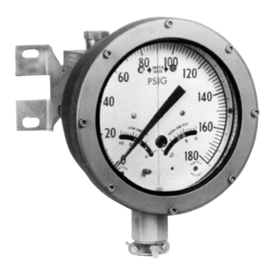
Model 580A-0 Switch
with Indicator
NUCLEAR MODEL 580A
®
DIFFERENTIAL PRESSURE
Part No. 9A-C10795, Rev. 03
SWITCH
User Manual
September 2015
Advertisement
Table of Contents
Troubleshooting

Subscribe to Our Youtube Channel
Related Manuals for Cameron BARTON 580A


Summary of Contents for Cameron BARTON 580A
-
Page 1: Table Of Contents
BARTON NUCLEAR MODEL 580A ® DIFFERENTIAL PRESSURE SWITCH User Manual Part No. 9A-C10795, Rev. 03 September 2015 Model 580A-0 Switch with Indicator Contents Safety ......................2 Section 1—Introduction ................. 3 General ......................3 Wiring ......................5 Differential Pressure Unit (DPU) ............... 5 Specifications .................... -
Page 2: Safety
Changing Switch Set Point ................. 20 Definitions of Terms ................. 20 Best Practices for Set Points ..............20 Changing Set Point of an In-Service Instrument (Not Recommended for Nuclear Qualified Units) ................21 Changing Set Point of an Out-of-Service Instrument ......22 Range Changes .................. -
Page 3: Section 1-Introduction
Model 580A Differential Pressure Switch Section 1 Section 1—Introduction General The 580A Differential Pressure Switch actuates single or dual signal circuits when predetermined limits of flow or level are exceeded. The DPU is con- nected to the process or vessel by tubing or piping. Changes in differential pressure (DP) at the DPU produce a mechanical output which moves a pointer and switch actuation controls. - Page 4 Section 1 Model 580A Differential Pressure Switch Actuating Cam Left Switch Right Switch Plunger Screw Plunger Screw Right Switch Left Switch Lock Screw Lock Screw Drive Arm Pointer Stop Bracket Switch Adjust Linkage Movement Assembly Left Switch Switch Adjust Linkage Adjustment Assembly* Terminal Strip...
-
Page 5: Wiring
Model 580A Differential Pressure Switch Section 1 Mid-point DP B O T H S W I T C HES RELAX ED C AM S W I T C H "A" S W I T C H "B " CLOSED OPEN SWITCH CONTACTS CONTACTS... -
Page 6: Specifications
± 2.5% of calibrated span for ranges between 400 and 600 psid; ±6% for ranges over 600 psid. Additional 2% is applicable near the switch setpoints (±10% span). Nuclear Qualifications The following nuclear qualification applications are based on Cameron Engi- neering Report 9A-CR3-580A-29 and 9A-CR3-580A31. Design Basis Event (DBE) Performance Error (% of calibrated span): Radiation (1 x 10 Rads) .... -
Page 7: Application Specifications
Model 580A Differential Pressure Switch Section 1 Application Specifications Model 580A switches were subjected to IEEE 323-1974/344-1975 qualifi- cation testing, which found the devices suitable for functional service in a limited harsh environment. The service conditions associated with the limited qualifications are: •... - Page 8 Section 1 Model 580A Differential Pressure Switch...
-
Page 9: Section 2-Installation
Model 580A Differential Pressure Switch Section 2 Section 2—Installation The instrument should be inspected at time of unpacking to detect any dam- age that may have occurred during shipment. IMPORTANT: The DPU was checked for accuracy at the factory. Do not change any of the settings during examination or accuracy could be affected. -
Page 10: Startup
Section 2 Model 580A Differential Pressure Switch IMPORTANT: Arc suppression for inductive loads will prolong the life of the switch contacts. Startup For startup procedures, warnings, and other information on the Model 224 DPU, see Appendix A, page A-1. IMPORTANT: To ensure the unit calibration is within factory-set calibration tolerances, perform the Calibration Check procedure on page Switch Wiring... -
Page 11: Section 3-Maintenance And Calibration
Model 580A Differential Pressure Switch Section 3 Section 3—Maintenance and Calibration The following checks are recommended for preventive maintenance: • Periodically inspect the alarm switch mechanism to verify that all mount- ing screws are seated properly. • Inspect linkage for wear. •... -
Page 12: Tools
Section 3 Model 580A Differential Pressure Switch Tools The following tools are recommended for general maintenance of the Model 580A differential pressure switch. Table 3.1—Tools Equipment Purpose Pointer Puller Pointer removal Small Screwdriver Calibration adjustment Medium Screwdriver Bezel removal and replacement 1/4"... -
Page 13: Pointer Installation And Removal
Model 580A Differential Pressure Switch Section 3 Replace the bezel/lens assembly. Pointer "slipped" rotated on hub Hub held in place with 1/4" wrench Figure 3.2—"Slipping" pointer To test for reverse travel, connect the pressure source to the low-pressure (LP) housing and vent the HP housing. Apply pressure to approximately 150% of the DP range. -
Page 14: Pointer Removal
Section 3 Model 580A Differential Pressure Switch Lightly tap the pointer hub with a hand-set or other flat-end tool. Use perpendicular blows to avoid bending the shaft. Check the calibration of the indicating switch over its entire range (refer Indicator Calibration, page 15). -
Page 15: Indicator Calibration
Model 580A Differential Pressure Switch Section 3 To remove the scale plate, move the pointer to the 12 o'clock position, remove the screws from the scale plate, and gently guide the scale plate halves from beneath the bottom mounting tab. Screws are located at 12, 3 and 9 o'clock positions and near the center of the plate which overlays a narrow bracket. - Page 16 Section 3 Model 580A Differential Pressure Switch Release pressure. Set the pointer to zero, by slipping the pointer on the hub, per step 2 of Calibration Check, page Repeat steps 4 and 5, as necessary, to obtain the correct zero/full-scale. Apply 50% DP.
-
Page 17: Drive Arm Tightness Test
Model 580A Differential Pressure Switch Section 3 10. Apply 0%, 25%, 50%, 75%, 100%, 75%, 50%, 25%, and 0% of full-scale differential pressure consecutively to the instrument without overshoot. Lightly tap the indicator to overcome friction. The pointer should accu- rately indicate each applied pressure. -
Page 18: Switch Calibration
Section 3 Model 580A Differential Pressure Switch Apply sufficient pressure to the low pressure housing to deflect the pointer against the zero stop post lock on the scale plate. Bend the zero drive arm stop against the drive arm. Verify calibration as applicable. Switch Calibration Before performing a complete calibration of the switch, perform a calibration check (See... -
Page 19: Linkage Calibration Procedure
Model 580A Differential Pressure Switch Section 3 Linkage Calibration Procedure The switch linkage should be calibrated whenever the Model 580A switch has been rebuilt. To calibrate the switch linkage, perform the following steps. Refer to Figure as needed. Loosen the three linkage screws and turn the crank to the 12 o’clock position. -
Page 20: Changing Switch Set Point
Section 3 Model 580A Differential Pressure Switch the pressure system to stabilize. Then change the pressure by a small amount. The magnitude of the pressure change is determined by the desired accuracy of the test. Tighten the lock screw before testing the switch performance. -
Page 21: Changing Set Point Of An In-Service Instrument (Not Recommended For Nuclear Qualified Units)
Model 580A Differential Pressure Switch Section 3 remove the scale plate and inspect the switch and the switch mechanism. The scale plate is split to allow for removal without pulling the pointer. Changing Set Point of an In-Service Instrument (Not Recommended for Nuclear Qualified Units) Use the following procedure to set a set point for an instrument that is in ser- vice, when calibration pressures cannot be applied. -
Page 22: Changing Set Point Of An Out-Of-Service Instrument
Section 3 Model 580A Differential Pressure Switch Example: Scale has range of 0-60 psid. Set point is 24 psid, with decreasing pressure, (24/60 x 10 = 4). Move the index pointer (item C) for the low switch from division 0 to division 4 tick mark. -
Page 23: Troubleshooting
Model 580A Differential Pressure Switch Section 3 Troubleshooting For switch troubleshooting tips, see Table 3.2 below. For information related to the Model 224 DPU, see Table A.3, page A-15. Table 3.2—Troubleshooting Problem Possible Probable Cause Corrective Source Action Low or No Indicator, Loose linkage or movement Tighten or replace... - Page 24 Section 3 Model 580A Differential Pressure Switch Table 3.2—Troubleshooting Problem Possible Probable Cause Corrective Source Action Switch Process Transients or surges cause switches to actu- Add time delay Drifts Changes ate prematurely gages or add time (set point circuit not repeat- Set point and/or deadband are too wide in Specify DP range as able)
-
Page 25: Section 4-Assembly Drawing And Parts List
Model 580A Differential Pressure Switch Section 4 Section 4—Assembly Drawing and Parts List LOCATE THE SCALE PLATE UNDER THE MOUNTING TAB WITHOUT A SCREW AT THE 6 O’CLOCK POSITION. Figure 4.1—Model 580A-0 indicating switch (shown with glass lens) - Page 26 Section 4 Model 580A Differential Pressure Switch Table 4.1 contains components for Model 580A-0 indicating switches and Model 580A-2 blind switches with internal indicator. For parts list information on Model 580A-2 blind switches without indicator, Table 4.2, page Table 4.1—Parts List, Model 580A-0 Indicating Switch and Model 580A-2 Blind Switch with Internal Indicator Item Description Part No.
- Page 27 Model 580A Differential Pressure Switch Section 4 Table 4.1—Parts List, Model 580A-0 Indicating Switch and Model 580A-2 Blind Switch with Internal Indicator Item Description Part No. Unit Bezel (Model 580A-0 only) 9A-C0580-1125C Lens Gasket (Model 580A-0 only) 9A-C0580-1126C Bracket (Switch to DPU) 9A-C0580-1059C Header Assembly 9A-C0580-1018B Screw, Cap:10-32 (select one) Model 580A-0 (with glass lens), 1" long 9A-C0220-1062J Model 580A-2 (blind with indicator), 1/2"...
- Page 28 Section 4 Model 580A Differential Pressure Switch Figure 4.2—Model 580A-2 blind switch without indicator...
- Page 29 Model 580A Differential Pressure Switch Section 4 Table 4.2 contains components for Model 580A-2 blind switches without indicator. For parts list information on Model 580A-0 indicating switches and Model 580A-2 blind switches with internal indicator, see Table 4.1, page Table 4.2—Parts List, Model 580A-2 Blind Switch without Indicator Item Description Part No.
- Page 30 Section 4 Model 580A Differential Pressure Switch Table 4.2—Parts List, Model 580A-2 Blind Switch without Indicator Item Description Part No. Unit Nut, Hex., 3/8-16 9A-C0500-0039J O-ring (Lens/Cover), EPT 9A-C0001-1057R O-ring (Plug), EPT 9A-C0001-1051R Screw, Rd. Hd., Slotted, 6-32 x 3/16 Lg. 9A-C0117-0013J Screw, Flat Hd., 10-32 x 1/2 Lg. 9A-C0240-0015J Washer, Split Lock, #8 9A-C0003-0036K...
- Page 31 Model 580A Differential Pressure Switch Section 4 Table 4.3 presents torque requirements for the switch assembly fasteners. Table 4.3—Torque Requirements for Switch Assembly Fasteners (See Figures 4.1 and 4.2 for part identification) Item Description Part No. Torque* Unit Lock Screw 9A-C0580-1017C Tight Screw, B.H. Slotted, 3-48 x 3/16 9A-C0117-0007J Tight Screw, B.H. Slotted, 8-32 x 3/16 9A-C0117-1001J Tight Set Screw, 6-32 x 1/4 Lg.
- Page 32 Section 4 Model 580A Differential Pressure Switch...
-
Page 33: Section 5-Dimensional Drawings
Model 580A Differential Pressure Switch Section 5 Section 5—Dimensional Drawings PRESSURE CONNECTIONS (WALL) CENTER OF GRAVITY 7 1/2 (190.5) CASE (19.1) (12.7) (127.0) 2 3/4 (69.9) 3 7/8 (98.4) Figure 5.1—Model 580A, side view TOP PRESSURE CONNECTIONS 2 5/16 CENTER OF GRAVITY 1/2 NPT STANDARD (58.7) HIGH PRESSURE... - Page 34 Section 5 Model 580A Differential Pressure Switch Table 5.1—Model 580A Dimensions DIM A DIM A DPU SWP DIM B DIM C DIM D DIM E (580A-0) (580A-2) .5/1.5K 7 5/16 6 3/4 6 15/16 5 5/8 5 1/16 2 15/16 185.7) (171.4) (176.2)
-
Page 35: Appendix A-Model 224 Dpu
Model 580A Differential Pressure Switch Appendix A Appendix A—Model 224 DPU DPU Description The Barton Model 224 Differential Pressure Unit (DPU) is a mechanical device that measures differential pressure relative to a gas or liquid flowing through a process system, or to the level of a liquid contained in a process vessel. - Page 36 Appendix A Model 580A Differential Pressure Switch The BUA with 3/4-inch bellows accommodates differential pressures up to 400 psi. The range springs are grouped around the outside of the bellows and must be of a material that is compatible with the liquid being measured. The BUA with 5/8-inch bellows accommodates differential pressure ranges up to 1000 psi.
-
Page 37: Theory Of Operation
Model 580A Differential Pressure Switch Appendix A Table A.1—Model 224 DPU Specifications BODY AVAILABLE DIFFERENTIAL PRESSURE RANGES Stainless Steel/Inconel Bellows Inconel Bellows psi (bar) Housing Material 1-5/8" (41.3 mm) O.D. 3/4" (19.1 mm) O.D. 5/8" (15.9 mm) O.D. Stainless Steel (316) 0-30" (0-762 mm) w.c. 0-61 psi (0-3.9 bar) to 0-400 psi (0-27.6 bar) to Copper Nickel (70-30) to 0-60 psi (0-3.8 bar) 0-400 psi (0-27.6 bar) 0-500 psi (0-34.5 bar) -
Page 38: Dpu Installation
Appendix A Model 580A Differential Pressure Switch Figure A.2—Model 224 DPU components required to actuate process instruments, such as recorders, indicators, trans- mitters, controllers, and switches. If the bellows are subjected to a pressure greater than the range of the DPU, they move their normal travel range and a small amount of overtravel until the overrange valve seals against the valve seat. -
Page 39: Mounting
Model 580A Differential Pressure Switch Appendix A For applications requiring special cleaning/precautions, a polyethylene bag is used to protect the instrument from contamination. Remove this bag only under conditions of extreme cleanliness. Mounting Mount the instrument to a solid support with four 5/16-inch (8 mm) grade 5 or better bolts, and apply 17 ft-lb of torque. -
Page 40: Piping Diagrams
Appendix A Model 580A Differential Pressure Switch • Mount the DPU on a solid support to minimize vibration. Tighten all points, using a suitable sealant compound; leaks in piping can cause measurement errors. • Rotate the housing as necessary to place the pressure connection in the proper position. - Page 41 Model 580A Differential Pressure Switch Appendix A SHUT-OFF VALVES BYPASS VALVE PRIMARY DEVICE BLOCK VALVES Figure A.5—Gas Flow, Hydrates Present PRIMARY DEVICE PLUGS BLOCK VALVES CONDENSING RESERVOIR SHUT-OFF VALVES VENT VALVES (OPTIONAL) Figure A.6—Steam Flow, DPU Below Run VENT BYPASS VALVE VALVES STATIC PRESSURE...
- Page 42 Appendix A Model 580A Differential Pressure Switch PRIMARY DEVICE FILL TEE AND VENT VALVE FOR HOT OR GASSY LIQUIDS BLOCK VALVES SHUT-OFF VALVES BYPASS VALVE Figure A.8—Liquid Flow, DPU Below Run BYPASS VALVE SHUT-OFF SEAL VALVES POTS PRIMARY DEVICE BLOCK VALVES Figure A.9—Corrosive Liquid Flow BLOCK...
- Page 43 Model 580A Differential Pressure Switch Appendix A BLOCK VALVE SHUT-OFF VALVE BLOCK VALVE SHUT-OFF VALVE DRAIN VALVE HIGH-PRESSURE Figure A.11—Cool Non-Condensing Liquid, DPU Below Tank 2" CROSS BLOCK REFERENCE VALVE VENT SHUT-OFF VALVE VALVE BLOCK VALVE SHUT-OFF HIGH-PRESSURE VALVE BYPASS DRAIN VALVE VALVE Figure A.12—DPU Bottom Tank with Reference Leg...
- Page 44 Appendix A Model 580A Differential Pressure Switch BLOCK VALVE INVERTED "U" GAS TRAP BLOCK VALVE MINIMUM LENGTH DRAIN 6 INCHES SHUT-OFF VALVE VALVE VAPOR GENERATOR LOW-PRESSURE Figure A.13—Liquid CO2 BLOCK VALVE MINIMUM LENGTH 12 INCHES INVERTED "U" GAS TRAP VAPOR GENERATOR FLAT TUBULAR SPIRAL IN OUTER 1/3 OF TANK INSULATION KEEP...
- Page 45 Model 580A Differential Pressure Switch Appendix A SIGHT FLOW GAGE BLOCK VALVES INPUT GAS REGULATOR SUPPLY SHUT-OFF VALVES BYPASS VALVE HIGH PRESSURE Figure A.15—Bubbler System SIGHT FLOW GAGES WITH THROTTLING VALVES INPUT GAS REGULATOR BLOCK VALVES SHUT-OFF VALVES SUPPLY BYPASS VALVE HIGH-PRESSURE Figure A.16—Liquid Specific Gravity A-11...
-
Page 46: Startup
Appendix A Model 580A Differential Pressure Switch Startup Observe the following practices when starting up a process monitoring instru- ment: 1. Close the block valves. 2. Perform a zero check on the instrument as follows. Open the bypass valve(s), then open one shutoff valve. This proce- dure equalizes the pressure between both sides of the instrument. -
Page 47: Dpu Cleaning And Inspection
Model 580A Differential Pressure Switch Appendix A W ARNING: The unexpected release of internal pressure from a DPU can result in severe personal injury, death or property damage. Before remov- ing DPU housing bolts, perform a pressure check. This is especially im- portant if the DPU is installed in a gas application with working pressures exceeding 200 psig. DPU Cleaning and Inspection Remove the DPU from service. Check for internal DPU pressure as follows: Back off all housing bolts 4 turns. Attempt to move the housing in and out along the bolts If the housing moves freely, no pressure is present. -
Page 48: Changing The Dpu Range
3/8-24 x 2.5 Notes: (1) Lubricant: Molykote G paste, graphite-base grease, or similar lubricants. Lube first thread only. (2) Torque on bolts is accomplished in 3 or 4 steps. Tighten uniformly. (3) Cameron recommends using a torque wrench whenever installing housing bolts. Rotation of bolt head is measured after bolt is "snug" (approx. 1/16 turn past head contact) with approximately 2 ft-lb torque. -
Page 49: Dpu Troubleshooting
Model 580A Differential Pressure Switch Appendix A Immediately stop all disassembly, tighten the housing bolts, and return the unit to the factory or authorized service center for repair. Tag the unit and specify "Gas in the Bellows." Carefully remove the pressure housing bolts and pressure housings. IMPORTANT: It is recommended that new O-rings be used whenever pressure hous- ings are replaced. - Page 50 Appendix A Model 580A Differential Pressure Switch Table A.3—Troubleshooting Tips Problem Possible Probable Cause Corrective Action Source Low or No Bellows Unit Housing filled with solids restricting bel- Clean out housing Indication lows movement Gas (liquid service) or liquid (gas service) Vent housing trapped in housing High pressure housing gasket leaks Replace gasket...
-
Page 51: Dpu Assembly Drawing And Parts List
Model 580A Differential Pressure Switch Appendix A DPU Assembly Drawing and Parts List Figure A.17—Model 224 DPU assembly drawing A-17... - Page 52 Appendix A Model 580A Differential Pressure Switch Table A.4—Model 224 DPU Parts List Item Description Part No. Bellows Unit Assembly, 3/4" or 5/8" Bellows Unit Assembly, 1-5/8" O-Ring, Housing Gasket Viton 9A-C0001-0039R 9A-C0001-1054R Bracket, Mounting 9A-C0273-0001C Washer, ET Lock, 1/4" SST 9A-C0003-0068K Screw, Hex Hd.
-
Page 53: Dpu Dimensional Drawing
Model 580A Differential Pressure Switch Appendix A DPU Dimensional Drawing Figure A.18—Model 224 DPU dimensional drawing Table A.5—Model 224 DPU Dimensions Dim "A" Dim "B" DIM "C" DIM "D" DIM "E" (psi) in. (mm) in. (mm) in. (mm) in. (mm) in. (mm) 500 or 2-15/16 5-5/8 6-15/16 4-3/4 3-1/8 1500 (74.6) (142.9) (176.2) (120.6) (79.4) - Page 54 Appendix A Model 580A Differential Pressure Switch A-20...
- Page 55 Cameron agrees to repair or furnish a replacement for, but not install, any product which within one (1) year from the date of shipment by Cameron shall, upon test and examina- tion by Cameron, prove defective within the above warranty.
Need help?
Do you have a question about the BARTON 580A and is the answer not in the manual?
Questions and answers