Nordmann Engineering AT4 D Installation And Operating Instructions Manual
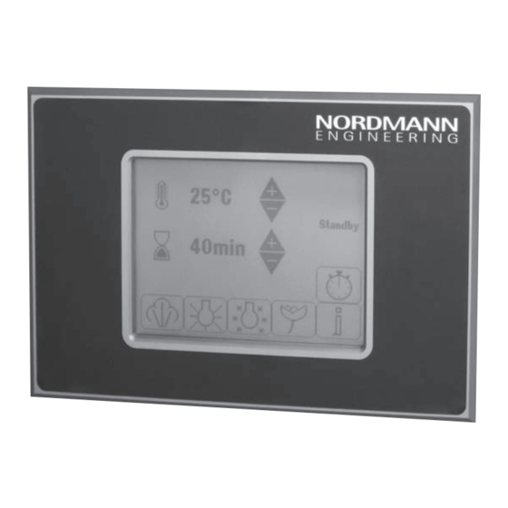
External steam bath control with touch-sensitive display
Hide thumbs
Also See for AT4 D:
- Operating instructions manual (76 pages) ,
- Installation and operation manual (32 pages) ,
- Service manual (36 pages)
Table of Contents
Advertisement
Available languages
Available languages
Quick Links
NORDMANN
E N G I N E E R I N G
Nordmann
Touch Panel
Externe Dampfbadsteuerung mit berührungssensitiver Anzeige
External steam bath control with touch-sensitive display
Commande externe de bain turc avec affichage tactile
MONTAGE- UND BETRIEBSANLEITUNG
INSTALLATION AND OPERATING INSTRUCTIONS
INSTRUCTIONS D'INSTALLATION ET D'EXPLOITATION
2568265 DE/EN/FR 1310
Advertisement
Chapters
Table of Contents

Subscribe to Our Youtube Channel
Related Manuals for Nordmann Engineering AT4 D


Summary of Contents for Nordmann Engineering AT4 D
- Page 1 NORDMANN E N G I N E E R I N G Nordmann Touch Panel Externe Dampfbadsteuerung mit berührungssensitiver Anzeige External steam bath control with touch-sensitive display Commande externe de bain turc avec affichage tactile MONTAGE- UND BETRIEBSANLEITUNG INSTALLATION AND OPERATING INSTRUCTIONS INSTRUCTIONS D’INSTALLATION ET D’EXPLOITATION 2568265 DE/EN/FR 1310...
-
Page 3: Table Of Contents
Standort wählen Gerät montieren 4.4.1 Dampfbadsteuerung für Unterputzmontage 4.4.2 Dampfbadsteuerung für Aufputzmontage Dampfbadsteuerung am Nordmann AT4 D anschliessen Nordmann AT4 D für den Betrieb mit der externen Dampfbadsteuerung konfigurieren Bedienung Betriebsanzeigen Dampfproduktion ein- und ausschalten Dampfbadbeleuchtung ein- und ausschalten Duftstoffintensität einstellen /Duftstoff ein- und ausschalten... -
Page 4: Einleitung
Arbeit ausreichend qualifiziertes Personal. Die Betriebsanleitung wird ergänzt durch die Betriebsanleitung zum Nord- mann AT4 D. Wo nötig finden sich in dieser Betriebsanleitung entsprechende Querverweise auf diese Dokumentation. In dieser Dokumentation verwendete Symbole VORSICHT! Das Signalwort “VORSICHT”... - Page 5 GEFAHR! Das Signalwort “GEFAHR” zusammen mit dem allgemeinen Gefahren- symbol kennzeichnet Sicherheits - und Gefahrenhinweise in dieser Doku- mentation, deren Miss achtung schwere Verletzungen einschliesslich den Tod von Personen zur Folge haben können. Aufbewahrung Die Betriebsanleitung an einem siche ren Ort aufbewahren, wo sie jederzeit zur Hand ist.
-
Page 6: Zu Ihrer Sicherheit
Gerät spielen. Bestimmungsgemässe Verwendung Die externe Dampfbadsteuerung Nordmann TP ist ausschliesslich zur Steuerung des Dampferzeugers Nordmann AT4 D innerhalb der spezifi- zierten Betriebs bedingungen (siehe Kapitel 8 “Gerätespezi fikationen”) bestimmt. Jeder andere Einsatz ohne schriftliche Genehmigung des Her- stellers gilt als nicht bestimmungsgemäss und kann dazu führen, dass das System gefahrbringend wird. - Page 7 Verhalten im Gefahrenfall Wenn anzunehmen ist, dass ein gefahrloser Betrieb nicht mehr mög lich ist, so ist der Nordmann AT4 D umgehend ausser Betrieb zu setzen, vom Stromnetz zu trennen und gegen unbeabsichtigtes Einschalten zu si chern (siehe Betriebsanleitung zum Nordmann AT4 D). Dies kann unter folgenden Umständen der Fall sein:...
-
Page 8: Produktübersicht
Produktübersicht Dampfbadsteuerung für Unterputzmontage Dampfbadsteuerung für Aufputzmontage Berührungssensitive Anzeige Unterputzgehäuse Aufputzgehäuse Steuerprint Touch Panel Anschlussklemme LED Speisespannung Potentiometer für die Kontrasteinstellung... -
Page 9: Installation
Installation Gerät auspacken und Lieferumfang prüfen Gerät auspacken Öffnen Sie die Verpackung (Kartonschachtel 248 mm x 248 mm x 100 mm) und überprüfen Sie den Lieferumfang auf Vollständigkeit. Unvoll stän dige Lie- fe rungen werden von Ihrem Nordmann-Lieferanten umgehend ergänzt. Der Lieferumfang umfasst: Dampfbadsteuerung für Unterputzmontage –... -
Page 10: Standort Wählen
Standort wählen Beachten Sie folgende Hinweise für die Standortwahl für die Dampfbad- steuerung Nordmann TP: – Das Gerät nicht in explosions- und spritz was ser gefähr deten Räumen montieren. – Das Gerät darf nicht in der Dampfkabine montiert werden. – Gerät nach Möglichkeit in Augenhöhe montieren. - Page 11 2. Anschlusskabel (4-adrig, als Zubehör erhältlich) von hinten durch eine der vier Öffnungen in das Unterputzgehäuse einziehen. Anschliessend Kabel durch die Wandöffnung zum Dampfgenerator führen. 3. Unterputzgehäuse in die Wandöffnung einschieben, mit einer Wasser- waage ausrichten und mit den vier Schraubklammern befestigen (nur bei Hohlwand möglich).
-
Page 12: Dampfbadsteuerung Für Aufputzmontage
5. Anschlusskabel unter Beachtung der Angaben in Kapitel 4.5 am Nord- mann AT4 D anschliessen und die Funktionskontrolle durchführen. 6. Nach erfolgreicher Funktionskontrolle Touch Panel vorsichtig auf das Unterputzgehäuse aufsetzen (darauf achten, dass das Anschlusskabel nicht eingeklemmt wird) und mit den vier mitgelieferten Senkkopfschrau- ben am Unterputzgehäuse befestigen und die Dekorfolie aufkleben. - Page 13 2. Schraubenabdeckungen des Aufputzgehäuses nach aussen klappen, die vier Schrauben lösen und das Gehäuseunterteil entfernen. Gehäu- seunterteil anschliessend mit den mitgelieferten Schrauben an der Wand befestigen. Vor dem Festziehen der Schrauben Gehäuseunterteil mit einer Wasserwaage ausrichten. 3. Loch für die Kabelverschraubung am gewünschten Ort in die Seitenwand des Gehäuseunterteils bohren und Kabelverschraubung montieren.
- Page 14 Touch Panel anbringen. 5. Anschlusskabel unter Beachtung der Angaben in Kapitel 4.5 am Nord- mann AT4 D anschliessen und die Funktionskontrolle durchführen. 6. Nach erfolgreicher Funktionskontrolle das Touch Panel vorsichtig auf das Gehäuseunterteil aufsetzen (darauf achten, dass das Anschlusskabel nicht eingeklemmt wird), mit den vier Schrauben am Gehäuseunterteil...
-
Page 15: Dampfbadsteuerung Am Nordmann At4 D Anschliessen
6. Bei korrekter Verkabelung erscheint nach dem Start des Nordmann AT4 D in der Anzeige der Dampfbadsteuerung die Standby-Betriebsanzeige (siehe Kapitel 5.1) oder falls der Nordmann AT4 D noch nicht korrekt kon- figuriert ist die Modbus-Fehlermeldung (Konfiguration siehe Kapitel 4.6). -
Page 16: Nordmann At4 D Für Den Betrieb Mit Der Externen Dampfbadsteuerung Konfigurieren
Nordmann AT4 D für den Betrieb mit der externen Dampfbadsteuerung konfigurieren Hinweis: Detaillierte Angaben zur Bedienung der Steuerungsoftware des Nordmann AT4 D finden sich in der Betriebsanleitung zum Nordmann AT4 D. Modbusparameter für die Kommunikation festlegen Legen Sie im Modbus-Untermenü “Remote” die Parameter wie folgt fest (Pfad: Menu >... -
Page 17: Bedienung
Bedienung Betriebsanzeigen Mit dem Anschluss der externen Dampfbadsteuerung am Nordmann AT4 D und der entsprechenden Konfiguration des Nordmann AT4 D ist die Dampf- badsteuerung betriebsbereit. Sobald der Dampferzeuger Nordmann AT4 D eingeschaltet wird, erscheint nach dem Aufstarten des Dampferzeugers die Standby-Betriebsanzeige (siehe unten). -
Page 18: Dampfproduktion Ein- Und Ausschalten
45min (Statusanzeige “Drying”) oder die Steuerung kehrt in den Standby-Betrieb (Statusanzeige “Standby”) zurück. Hinweis: Abhängig von der Konfiguration des Nordmann AT4 D muss das Licht manuell über die Tasten (Licht 1) oder (Licht 2) 42°C ausgeschaltet werden (siehe Kapitel 5.3) oder... -
Page 19: Dampfbadbeleuchtung Ein- Und Ausschalten
42°C Standby 45min Duftstoffintensität einstellen /Duftstoff ein- und ausschalten Hinweis: Die Einstellungen der Duftstoffintensität werden automatisch zwi- schen der Steuerung des Nordmann AT4 D und der Dampfbadsteuerung abgeglichen. In der Betriebsanzeige (Standby- oder Dampf- badbetrieb) die Taste antippen. 42°C... -
Page 20: Badezeit Einstellen
5...240 Minuten). 45min Uhrzeit einstellen Die aktuelle Uhrzeit wird automatisch zwischen der Steuerung des Nordmann AT4 D und der Dampfbadsteuerung abgeglichen. Falls die Uhrzeit nicht korrekt eingestellt ist, ändern Sie die Uhrzeit über die Dampfbadsteuerung wie folgt: In der Standby-Betriebsanzeige Taste 42°C... -
Page 21: Timer Einstellen/Aktivieren
Timer einstellen/aktivieren Über die Dampfbadsteuerung kann ein timergesteuerter Badebetrieb konfi- guriert und aktiviert werden. Ist der Timer aktiviert wird der Dampfgenerator automatisch zur festgelegten Tageszeit und für die festgelegte Dauer einge- schaltet. Die Timersteuerung wird nach dem Badebetrieb immer deaktiviert und muss für jeden Tag neu aktiviert werden. - Page 22 Die Infoanzeige erscheint. Angezeigt wer- den: 25(32)kg/h TP-V1.01 1. Softwareversion der Dampfbadsteue- rung Error 14 Warning 28 2. Dampfleistung des Dampfzylinders 3. Fehlerstatus (die letzten beiden Störun- gen werden angezeigt oder o.k. falls keine Störung vorhanden ist) 25(32)kg/h Taste antippen, um zur Betriebsanzeige TP-V1.01 zurückzukehren.
-
Page 23: Störungen
Error-Meldung 14 “Dampfbadtüre offen” Error Error 14 (das Symbol erscheint zusätzlich in der Betriebsanzeige) Modbus Error 35 Modbus-Error (Error 35 “Modbus Timeout”) Reg.(R):40026 Hinweis: Detaillierte Angaben zu den Störungen finden Sie in den Störungs- listen in der Betriebsanleitung zum Nordmann AT4 D. -
Page 24: Störungen Ohne Anzeige
– Kabel korrekt anschliessen. angeschlossen. – Steuer- und/oder Leistungs- – Steuer- und/oder Leistungs- print des Nordmann AT4 D print des Nordmann AT4 D defekt. kontrollieren/ersetzen. Hinweis: Die grüne Kontroll-LED (Power) auf dem Steuerprint der Dampfbadsteuerung leuchtet (nur sichtbar, bei ausgebautem Touch Panel), wenn die 24 VDC Speisespannung vorhanden ist. -
Page 25: Ausserbetriebsetzung/Entsorgung
Muss die externe Dampfbadsteuerung Nordmann TP ersetzt werden oder wird die Dampfbadsteuerung nicht mehr benötigt, gehen Sie wie folgt vor: 1. Dampferzeuger Nordmann AT4 D ausschalten, vom Stromnetz trennen und gegen unbeabsichtigtes Einschalten sichern. 2. Externe Dampfbadsteuerung (und falls erforderlich andere Systemkom- ponenten) durch einen Fachmann ausbauen lassen. -
Page 26: Technische Daten
Technische Daten Externe Dampfbadsteuerung Nordmann TP Version Unterputz Version Aufputz Touch Panel Analog Touch Panel mit 120 x 90 mm aktiver Fläche Anzeige 5,7" 1/4 VGA LCD, 320x240 Pixel Kontrast einstellbar via Potentiometer Schnittstelle RS485 Speisespannung 8…30 VDC Zulässige Umgebungstemperatur -20…70°C Zulässige Umgebungsfeuchte 10... - Page 27 4.4.1 Steam bath control for in-wall mounting 4.4.2 Steam bath control for on-wall mounting Connecting the steam bath control to the Nordmann AT4 D Configuring the Nordmann AT4 D for the operation with the external steam bath control Operating Operating displays...
-
Page 28: Introduction
Nordmann TP and is meant for well trained personnel being sufficiently qualified for their respective work. The operating instructions are supplemented by the operating instructions for the steam generator Nordmann AT4 D. Where necessary, appropriate cross-references are made to this publications in the operating instructions. Symbols used in this manual CAUTION! The catchword “CAUTION”... - Page 29 DANGER! The catchword “DANGER” used in conjunction with the general caution symbol designates safety and danger notes in this documentation that, if neglected, may lead to severe injury or even death of persons. Safekeeping Please safeguard this operating instructions in a safe place, where it can be immediately accessed.
-
Page 30: For Your Safety
Intended use The external steam bath control Nordmann TP is intended exclusively for the control of the steam generator Nordmann AT4 D within the specified operating conditions (see chapter 8 “Product specifications”). Any other type of application without the express written consent of the manufacturer is considered as not conforming with the intended purpose and may lead to the system becoming dangerous. - Page 31 If it is suspected that safe operation is no longer possible, then the Nordmann AT4 D should immediately be set out of operation, discon- nected from the mains and secured against accidental power-up (see operating instructions for Nordmann AT4 D). This can be the case under the following circumstances: –...
-
Page 32: Product Overview
Product Overview Steam bath control for in-wall mounting Steam bath control for on-wall mounting Touch-sensitive display In-wall housing On-wall housing Control board touch panel Connecting terminal LED supply voltage Potentiometer contrast adjustment... -
Page 33: Installation
Installation Unpacking and checking the scope of delivery Unpacking the unit Open the packing (cardboard box 248 mm x 248 mm x 100 mm) and check the delivery for completeness. Please contact your Nordmann supplier in case something is lacking, they will be glad to send you the missing part without delay. -
Page 34: Choosing Location
Choosing location Please observe the following notes for the correct positioning of the external steam bath control Nordmann TP: – The unit must not be installed in hazardous locations and in rooms where water splashes may occur. – Do not mount the unit inside the steam bath cabin. –... - Page 35 2. Insert supply cable (four-core wire, available as accessory) from the back through on of the four openings into the in-wall housing, then lead the cable through the wall opening to the steam generator. 3. Insert the in-wall housing into the wall opening, align it with the help of a spirit level, then fix it with the four screw clamps (possible only with cavity wall) attached to the in-wall housing.
-
Page 36: Steam Bath Control For On-Wall Mounting
5. Connect the supply cable according to the specifications in chapter 4.5 to the Nordmann AT4 D, then perform the function control. 6. After successful function control carefully place the touch panel onto the in-wall housing (make sure the supply cable is not getting pinched). - Page 37 2. Swing out the screw covers on both sides of the on-wall housing. Undo the four screws, then remove the housing base. Fix housing base to the wall using the four screws supplied. Before tightening the screws align housing base with the help of a spirit level. 3.
- Page 38 5. Connect the supply cable according to the specifications in chapter 4.5 to the Nordmann AT4 D, then perform the function control.. 6. After successful function control carefully place the touch panel onto the housing base (make sure the supply cable is not getting pinched).
-
Page 39: Connecting The Steam Bath Control To The Nordmann At4 D
(ESD protection). 1. Remove front panel of the control compartment of the Nordmann AT4 D. 2. Insert the four-core wire from the bottom via a cable gland into the control compartment. -
Page 40: Configuring The Nordmann At4 D For The Operation With The External Steam Bath Control
Configuring the Nordmann AT4 D for the operation with the external steam bath control Note: Detailed information on the operation of the control software of the Nordmann AT4 D can be found in the operating instructions of the Nord- mann AT4 D. Setting the Modbus communication parameters In the Modbus submenu “Remote”... -
Page 41: Operating
Upon connection to the steam generator Nordmann AT4 D and the appropri- ate configuration of the Nordmann AT4 D the external steam bath control is ready for operation. As soon as the steam generator Nordmann AT4 D is switched on the standby operating display is shown (see below). -
Page 42: Switching On And Off The Steam Production
As soon as the bathing time has elapsed the steam production is automatically stopped. 42°C Depending on the configuration of the Nord- Drying mann AT4 D the drying process of the cabin 45min starts (status indication “Drying”) or the control returns to standby operation (status indication “Standby”). -
Page 43: Switching On And Off The Steam Bath Light
Setting the fragrance intensity /Switching on and off the fragrance dispensing Note: the fragrance intensity settings are automatically adjusted between the control of the Nordmann AT4 D and the steam bath control. In the operating display (standby or steam bath operation) tap on the key. -
Page 44: Setting The Bathing Time
Note: the time of day is automatically adjusted between the control of the Nordmann AT4 D and the steam bath control. If the time of day is not set correctly you can change the time via the steam bath control as follows: In the standby operating display tap on the key. -
Page 45: Setting/Activating The Timer
Setting/activating the timer Via the steam bath control a timer controlled bathing operation can be con- figured and activated. If the timer is activated, the steam generator starts at the set time of day and runs for the set duration. After the bathing time has elapsed the timer is deactivated and must newly be activated for each day. - Page 46 The info display appears. The following is shown: 25(32)kg/h TP-V1.01 1. Software version of the steam bath control Error 14 Warning 28 2. Steam capacity of the steam cylinder in use 3. Error status (the last two active error or warning messages are displayed or "o.k."...
-
Page 47: Malfunctions
(additionally the symbol is shown in the operating display) Modbus Error 35 Error message (Error 35 “Modbus Timeout”) Reg.(R):40026 Note: Detailed information regarding malfunctions can be found in the mal- functions list in the operating instructions of the Nordmann AT4 D. -
Page 48: Malfunctions Without Error Display
– Power board and/or control – Check/replace power board board of the Nordmann AT4 D and/or control board of the defective. Nordmann AT4 D. Note: the green control LED on control board of the external... -
Page 49: Taking Out Of Service/Disposal
If the external steam bath control Nordmann TP must be replaced or if the external steam bath control is not needed any more, proceed as follows: 1. Switch off the steam generator Nordmann AT4 D, separate it from the mains and secure it against inadvertent power-up. -
Page 50: Technical Data
Technical Data External steam bath control Nordmann TP In-wall version On-wall version Touch Panel Analogue Touch Panel with 120 x 90 mm active screen Display 5,7" 1/4 VGA LCD, 320x240 Pixel Contrast adjustable via potentiometer Interface RS485 Supply voltage 8…30 VDC Admissible ambient temperature -20…70°C Admissible ambient humidity... - Page 51 4.4.1 Unité de commande de bain de vapeur à encastrer 4.4.2 Unité de commande de bain de vapeur à poser en saillie Branchement de l’unité de commande de bain de vapeur au Nordmann AT4 D Configuration du Nordmann AT4 D pour le fonctionnement avec l’unité de commande...
-
Page 52: Introduction
Le présent mode d’emploi est complété par le mode d’emploi concernant le Nordmann AT4 D. Le cas échéant, vous trouverez dans le présent mode d’emploi toute référence à la documentation susmentionnée. Symboles utilisés dans cette documentation ATTENTION! L’expression “ATTENTION”... - Page 53 DANGER! L’expression “DANGER”, associée aux symboles généraux de danger, figurant dans la présente documentation, signale des indications de sécu- rité ou de danger dont la non-observation peut conduire à des blessures graves, voire à la mort de personnes. Sauvegarde Veuillez conserver le mode d’emploi en un endroit sûr, à porté de main. Remettre cette documentation à...
-
Page 54: Concernant Votre Sécurité
Utilisation conforme aux consignes La commande externe de bain de vapeur Nordmann TP est destinée uniquement à l’asservissement de l’humidificateur Nordmann AT4 D dans le contexte des conditions d’exploitations spécifiées (voir chapitre 8 “caractéristiques de l’appareil”. Toute autre utilisation sans autorisation écrite du fabricant est considérée comme non conforme et peut rendre le... - Page 55 Comportement en cas de danger Si l’on doit admettre qu’une exploitation sans danger n’est plus possible, mettre le Nordmann AT4 D immédiatement hors service, le déconnecter du réseau électrique et l’assurer contre tout enclenchement intempestif (consulter le mode d’emploi concernant le Nordmann AT4 D). Cette situation peut se présenter dans les cas suivants:...
-
Page 56: Vue D'ensemble Du Produit
Vue d’ensemble du produit Unité de commande de bain de vapeur Unité de commande de bain de vapeur à encastrer à poser en saillie Affichage tactile 2a Boîtier encastré 2b Boîtier à poser en saillie Platine de commande affichage tactile Borne de raccordement LED tension d'alimentation Potentiomètre pour le réglage du contraste... -
Page 57: Installation
Installation Déballage de l’appareil et contrôle de l’intégralité de la livraison Déballage de l’appareil Ouvrez l’emballage (boîte de carton 248 mm x 248 mm x 100 mm) et vérifiez la livraison quant à son intégralité. Si des composants font défaut, votre fournisseur Nordmann en effectuera le remplacement sans tarder. -
Page 58: Choix De L'emplacement
à des giclures d’eau, – ne pas monter l’appareil dans la cabine à vapeur, – l’éloignement de l’humidificateur Nordmann AT4 D doit permettre la pose et le raccordement corrects du câble de raccordement livré, – si possible, monter l’appareil à la hauteur des yeux, –... - Page 59 2. Tirer le câble de raccordement (4 brins, disponible en accessoires) à travers l’une des quatre ouvertures du boîtier encastrable. Amener ensuite le câble au générateur de vapeur par l’ouverture dans le mur. 3. Insérer le boîtier encastrable dans l’ouverture du mur, le mettre à niveau à...
-
Page 60: Unité De Commande De Bain De Vapeur À Poser En Saillie
5. Brancher le câble de raccordement conformément aux indications situées au Chapitre 4.5 du Nordmann AT4 D; procéder ensuite au contrôle de la fonction. 6. Après un contrôle de la fonction réussi, poser l’écran tactile avec pré- caution sur le boîtier encastrable (veiller à ne pas coincer le câble de raccordement), le fixer au boîtier encastrable à... - Page 61 2. Rabattre les caches-vis du boîtier apparent à l’extérieur, desserrer les quatre vis et retirer la base du boîtier. Fixer ensuite la base du boîtier au mur à l’aide des vis fournies. Avant de serrer les vis, mettre la base du boîtier à...
- Page 62 à la figure. 5. Brancher le câble de raccordement conformément aux indications situées au Chapitre 4.5 du Nordmann AT4 D; procéder ensuite au contrôle de la fonction. 6. Après un contrôle de la fonction réussi, poser l’écran tactile avec précaution sur la base du boîtier (veiller à...
-
Page 63: Branchement De L'unité De Commande De Bain De Vapeur Au Nordmann At4 D
Nordmann AT4 D Afin de brancher l’unité de commande externe de bain de vapeur sur le générateur de vapeur Nordmann AT4 D, il est nécessaire de suivre les instructions de montage du générateur de vapeur Nordmann AT4 D et d’observer la réglementation locale relative à l’exécution des ins- tallations électriques ! -
Page 64: Configuration Du Nordmann At4 D Pour Le Fonctionnement Avec L'unité De Commande Externe De Bain De Vapeur
à l’aide du potentio- mètre sur la platine de commande de l’unité de commande. Configuration du Nordmann AT4 D pour le fonctionnement avec l’unité de commande externe de bain de vapeur Remarque: de plus amples informations relatives à l’utilisation du logiciel de commande Nordmann AT4 D se trouvent dans les instructions d’exploitation... -
Page 65: Commande
Affichage d’exploitation Une fois que le branchement de l’unité de commande externe de bain de vapeur sur le générateur de vapeur Nordmann AT4 D ainsi que la configuration correspondante du Nordmann AT4 D sont effectués, la commande de bain de vapeur est opérationnelle. Lorsque le générateur de vapeur Nordmann AT4 D est activé, l’affichage de fonctionnement standby apparaît dès le... -
Page 66: Enclenchement Et Déclenchement De La Production De Vapeur
43°C passe en “Bathing”. En fonction de la confi- Bathing guration du générateur de vapeur Nordmann 40min AT4 D, la lumière s’allume automatiquement ou doit être allumée manuellement au moyen des touches (Lumière 1) ou (Lumière 2) (cf. Chapitre 5.3). -
Page 67: Enclenchement Et Déclenchement De L'éclairage Du Bain De Vapeur
“0” afin de désactiver une pompe à fragrance. Réglage de la température de consigne Remarque: La température de consigne est ajustée automatiquement entre la commande du générateur de vapeur Nordmann AT4 D et la commande du bain de vapeur. Définir la température de consigne (plage 42°C... -
Page 68: Réglage De La Durée De Bain
Réglage de l’heure L’heure actuelle est ajustée automatiquement entre la commande du géné- rateur de vapeur Nordmann AT4 D et la commande du bain de vapeur. Si l’heure n’est pas réglée correctement, celle-ci est à modifier dans la com- mande du bain de vapeur de la façon suivante: Appuyer sur la touche dans l’affichage de... -
Page 69: Réglage Et Activation Du Timer
Réglage et activation du timer Le fonctionnement de bain commandé par le timer peut être configurer et activer dans la commande du bain de vapeur. Si le timer est activé, le générateur de vapeur se déclenche automatiquement à l’heure définie et fonctionne pendant la durée déterminée. - Page 70 L’écran d’affichage d’informations apparaît et indique: 25(32)kg/h TP-V1.01 1. la version du logiciel de la commande de bain de vapeur Error 14 Warning 28 2. le débit de vapeur du cylindre à vapeur 3. l’état d’erreur (les deux dernières erreurs ou “o.k.”...
-
Page 71: Dérangements
Modbus Error 35 Erreur Modbus (erreur 35 “Modbus Timeout”) Reg.(R):40026 Remarque: Vous trouverez de plus amples informations relatives aux mes- sages d’erreur dans les Listes de dérangements des instructions d’exploitation du générateur de vapeur Nordmann AT4 D. -
Page 72: Erreurs Sans Affichage
Nordmann de puissance du générateur AT4 D défectueuse. de vapeur Nordmann AT4 D. Remarque: le voyant vert de contrôle sur l’électronique d’as- servissement de la commande externe de bain de vapeur est allumé... -
Page 73: Mise Hors Service/Évacuation
Si la commande externe de bain de vapeur Nordmann TP doit être rempla- cée ou si elle n’est plus utilisée, procédez comme suit: 1. Déclenchez le générateur de vapeur Nordmann AT4 D, déconnectez-le du réseau électrique et assurez-le contre tout enclenchement intempestif, 2. -
Page 74: Caractéristiques Techniques
Caractéristiques techniques Commande externe de bain de vapeur Nordmann TP Version encastrable Version en saillie Écran tactile Écran tactile analogique, surface active 120 x 90 mm Affichage 5,7" 1/4 VGA LCD, 320x240 Pixel Contraste réglable par potentiomètre Interface RS485 Tension d’alimentation 8…30 VDC Température ambiante admissible -20…70°C... - Page 75 © Nordmann Engineering Ltd., Printed in Switzerland Technische Änderungen vorbehalten Technical modifications reserved Sous réserve de modifications techniques...
- Page 76 Reg.No. 40002-2 NORDMANN Manufacturer: Nordmann Engineering Ltd. E N G I N E E R I N G www.nordmann-engineering.com, info@nordmann-engineering.com...
Need help?
Do you have a question about the AT4 D and is the answer not in the manual?
Questions and answers