Table of Contents
Advertisement
Available languages
Available languages
Quick Links
D
Gebrauchs- und Montageanweisung
Induktions-Glaskeramik-Kochfeld
GB
Instructions for fi tting and use
Glass ceramic induction hob
F
Instructions de montage et d'utilisation
Table de cuisson vitrocéramique à induction
I
Istruzioni per uso e montaggio
Piano di cottura ad induzione in vetroceramica
NL
Gebruiks- en montageaanwijzing
Keramische inductiekookplaat
CTDI K 840C NE
Advertisement
Chapters
Table of Contents

Subscribe to Our Youtube Channel
Related Manuals for Bauknecht CTDI K 840C NE


Summary of Contents for Bauknecht CTDI K 840C NE
- Page 1 Instructions for fi tting and use Glass ceramic induction hob Instructions de montage et d’utilisation Table de cuisson vitrocéramique à induction Istruzioni per uso e montaggio Piano di cottura ad induzione in vetroceramica Gebruiks- en montageaanwijzing Keramische inductiekookplaat CTDI K 840C NE...
-
Page 2: Table Of Contents
BAUKNECHT GEKAUFT HABEN 4.16 Abschaltautomatik (Timer) ........20 4.17 Kurzzeitwecker (Eier-Uhr) ........20 Für einen umfassenderen Kundenservice, registrieren Sie 4.18 Powerstufe ............21 Ihr Produkt bitte unter www.bauknecht.eu/ 4.19 Brückenfunktion ..........21 4.20 Powermanagement ..........21 Lesen Sie unbedingt die Sicherheitshinweise vor der Inbe- triebnahme Ihres Gerätes 4.21 Lüfter verwenden ..........22... -
Page 3: Sicherheits- Und Warnhinweise
Beschädigungen an der Glas- WICHTIG fl äche besteht bei Gebrauch Stromschlagge- Lesen und laden Sie die komplette Anleitung fahr. unter docs.bauknecht.eu runter oder rufen ACHTUNG: Feuergefahr! Die Kochzonen Sie die in der Garantieerklärung aufgeführte dürfen nicht als Ablagefl äche benutzt werden. Telefonnummer an. - Page 4 Sicherheits- und Warnhinweise INSTALLATION REINIGUNG UND WARTUNG Das Gerät muss immer von mindestens zwei ACHTUNG: Trennen Sie vor Reinigung und Personen bewegt und eingebaut werden - Un- Instandhaltung das Gerät von der Stromver- fallgefahr!. Tragen Sie beim Auspacken und sorgung; niemals Dampfreinigungsgeräte Einbau Schutzhandschuhe zur Vermeidung verwenden - Stromschlaggefahr.
- Page 5 Sicherheits- und Warnhinweise TIPPS ZUM ENERGIESPAREN VERPACKUNGSENTSORGUNG • Schalten Sie die Haube nur mit minimaler Ge- • Das Verpackungsmaterial ist zu 100% wie- schwindigkeit ein, wenn Sie mit dem Kochen derverwertbar und trägt das Recycling-Sym- begonnen und lassen Sie sie nur ein paar .
-
Page 6: Montageanleitung
Montageanleitung 2 Montageanleitung 2.3 Einbau Wichtige Hinweise 2.1 Sicherheitshinweise für den Küchenmöbelmonteur • Übermäßige Hitzeentwicklung von unten z.B. von ei- • Das Gerät muss immer von mindestens zwei Personen nem Backofen ohne Querstromlüfter ist zu vermeiden. bewegt und eingebaut werden - Unfallgefahr! Tragen Sie beim Auspacken und Einbau Schutzhandschuhe •... -
Page 7: Variable Einbaumöglichkeit: Aufl Iegender Einbau
Montageanleitung 2.4 Variable Einbaumöglichkeit: aufl iegender 2.5 Variable Einbaumöglichkeit: fl ächenbündiger Einbau Einbau Maße in mm 804+1 750+1 750+1 min.50 min.50 min.50 min.50 Dichtband in die Ecke der Aufl agekante der Arbeitsplatte aufkleben, so dass sich kein Silikonkleber unter das Koch- feld durchdrücken kann. -
Page 8: Abbildungen Küchenschrank
Montageanleitung 2.6 Abbildungen Küchenschrank Arbeitsplatte 600 mm max.430 ≥335 ≥170 max.430 NW150 NW150 max.300 Abluftauslass links Abluft wahlweise links oder rechts: Die Abluft kann je nach Einbausituation links oder rechts gewählt Abluftauslass rechts werden. Beachten Sie bitte hierzu die nebenste- henden Maße zur optimalen Planung. -
Page 9: Zusammenbau Abluftsystem
Montageanleitung 2.7 Zusammenbau Abluftsystem Abluftkanal-Komponenten (optional) Die Verbindung zwischen Kochfeld und Lüfter kann mit einem Flexschlauch oder einem Flachkanal erfolgen. Den Flachkanal nach Bedarf in der Länge mit einer Fein- säge kürzen. Variante Variante Flexschlauch Flachkanal Zu Punkt c Das fl exible Verbindungsstück wird bei einer Arbeitsplat- tentiefe von 600 mm verwendet. -
Page 10: Wichtige Hinweise Zum Einbau Des Kochmuldenlüfters
Montageanleitung 2.8 Wichtige Hinweise zum Einbau des Kochmul- • Die Nennweite der Umluftrohre darf 150 mm nicht unterschreiten. denlüfters • Abluftleitungen sollen so kurz wie möglich sein, nicht • Das Gerät muss immer von mindestens zwei Personen im 90 Grad-Winkel sondern in weichen Bögen geführt bewegt und eingebaut werden - Unfallgefahr! Tragen werden und keine Querschnittsreduzierungen haben. -
Page 11: 7-Poliger Stecker Anschluss Lüfter
Montageanleitung 2.9 7-poliger Stecker Anschluss Lüfter WARNUNG VOR ELEKTRISCHER Vorgehensweise ENERGIE! ES BESTEHT LEBENSGEFAHR! Für den Lüfteranschluss verbinden Sie die beiden 7-poli- gen Stecker. In der Nähe dieses Symbols sind span- nungsführende Teile angebracht. Abdeckun- Steckersicherung am 7 poligen Stecker (Lüfter) des Koch- feldes öff... -
Page 12: Einbau Kochmulden Lüfter
Montageanleitung 2.11 Einbau Kochmulden Lüfter Anschlusswerte Netzspannung: 380-415V 3N~, 50/60Hz • Das Produkt darf nur von einem zugelassenen Fach- mann unter Beachtung der örtlich geltenden Vorschrif- Komponentennennspannung: 220-240V ten angeschlossen werden, gleiches gilt für die Ab- luftanschlüsse. Der Installateur ist für die einwandfreie Anschlussleitung werkseitig vorhanden Funktion am Aufstellort verantwortlich! •... -
Page 13: Technische Daten
Montageanleitung 2.13 Inbetriebnahme 2.12 Technische Daten Nach dem Einbau des Feldes und nach dem Anlegen der Abmessungen Kochfeld Versorgungsspannung (Netzanschluss) erfolgt zuerst ein Höhe/ Breite/ Tiefe ..mm 170 x 800 x 520 Selbst-Test der Steuerung und es wird eine Serviceinfor- Kochzonen mation für den Kundendienst angezeigt. -
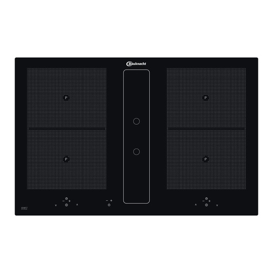
Page 14: Gerätebeschreibung
Gerätebeschreibung 3 Gerätebeschreibung Das Dekor kann von den Abbildungen abweichen. 10. Plus-Taste (erhöhen) / Minus-Taste (verringern) 11. Kochstufen-Anzeige 1. Induktionskochzone vorne links 12. Timeranzeige 2. Induktionskochzone hinten links 13. Stand-by Taste 3. Glaskeramik-Kochfeld 14. Minus- /Plus-Taste Lüfter 4. Touch-Control Bedienfeld 15. -
Page 15: Bedienung Durch Sensortasten
Gerätebeschreibung 3.1 Bedienung durch Sensortasten Kochstufen-Anzeige (11) Die Kochstufen-Anzeige zeigt die gewählte Kochstufe, Die Bedienung des Glaskeramik-Kochfeldes erfolgt durch oder: Touch-Control Sensortasten. Die Sensortasten funktio- nieren wie folgt: mit der Fingerspitze ein Symbol auf der leuchtet hell Kochzone ist ausgewählt (selektiert) Glaskeramikoberfl... -
Page 16: Bedienung
Bedienung 4 Bedienung 4.3 Betriebsdauerbegrenzung Das Induktionskochfeld besitzt eine automatische Be- 4.1 Das Induktionskochfeld triebsdauerbegrenzung. Die Kochfl äche ist mit einem Induktionskochfeld ausgestat- Die kontinuierliche Nutzungsdauer jeder Kochzone ist tet. Eine Induktionsspule unterhalb der Glaskeramik-Koch- abhängig von der gewählten Kochstufe (siehe Tabelle). fl... -
Page 17: Geschirr Für Induktionskochfeld
Bedienung 4.6 Geschirr für Induktionskochfeld 4.7 Energiespartipps Das für die Induktionskochfl äche benutzte Kochgefäß Nachfolgend fi nden Sie einige wichtige Hinweise, um ener- muss aus Metall sein, magnetische Eigenschaften haben giesparend und effi zient mit Ihrem neuen Induktionskoch- und eine ausreichende Bodenfl äche besitzen. feld und dem Kochgeschirr umzugehen. -
Page 18: Gerät Betriebsbereit Schalten
Bedienung 4.10 Gerät betriebsbereit schalten Mit der Stand-by Taste wird das Gerät betriebsbereit geschaltet. Die Taste ist sozusagen der Hauptschalter. Es erfolgt zuerst ein Selbst-Test der Steuerung und die Anzeigen leuchten kurz auf. Nach dem Ausschalten über diese Taste bleibt das Gerät noch ca. -
Page 19: Verriegelung
Bedienung 4.15 Verriegelung Die Verriegelung soll verhindern, dass Kinder versehent- lich oder absichtlich das Kochfeld einschalten. Dazu wird die Bedienung gesperrt. Verriegelung einschalten 1. Ein-/Aus-Taste Kochfeld betätigen um das gesamte Kochfeld einzuschalten. 2. Gleich darauf die Minus-Taste und die rechts dane- ben liegende Kochzonenauswahl-Taste gleichzeitig betätigen. -
Page 20: Abschaltautomatik (Timer)
Bedienung 4.16 Abschaltautomatik (Timer) Durch die Abschaltautomatik wird jede eingeschaltete Kochzone nach einer einstellbaren Zeit automatisch ab- geschaltet. Es können Kochzeiten von 01 bis 99 Minuten eingestellt werden. 1. Das Kochfeld einschalten. Eine oder mehrere Koch- zonen einschalten und gewünschte Kochstufen wählen. -
Page 21: Powerstufe
Bedienung 4.18 Powerstufe Die Powerstufe stellt den Induktionskochzonen zusätzliche Leistung zur Verfügung. Eine große Menge Wasser kann schnell zum Kochen gebracht werden. Die Powerstufe arbei- tet für 5 Minuten, anschließend wird automatisch auf Kochstu- fe 9 zurückgeschaltet. 1. Das Kochfeld einschalten. 2. -
Page 22: Lüfter Verwenden
Bedienung 4.21 Lüfter verwenden In der Mitte des Kochfeldes befi ndet sich der Lüfter mit dem Abzug nach unten. Wichtig: Abdeckung nicht auf dem Induktionskochfeld ablegen! Verbrennungsgefahr! 4.21.1 Lüfter ein- und ausschalten 1. Stand-by Taste betätigen (ca. 1 Sek.) 2. Die Plus-Taste vom Lüfter betätigen. -
Page 23: Reinigung Und Pfl Ege
Reinigung und Pfl ege 5 Reinigung und Pfl ege Kochfeldes, sondern um nicht entfernte und daher einge- brannte Rückstände. • Vor dem Reinigen das Kochfeld ausschalten und ab- Glanzstellen entstehen durch Abrieb des Topfbodens, kühlen lassen. insbesondere bei Verwendung von Kochgeschirr mit Alu- •... -
Page 24: Was Tun Bei Problemen
Was tun bei Problemen? 6 Was tun bei Problemen? Der Fehlercode U400 wird angezeigt? Das Kochfeld ist falsch angeschlossen. Die Steuerung Unqualifi zierte Eingriff e und Reparaturen am Gerät sind schaltet nach 1s ab und es ertönt ein Dauersignalton. Die gefährlich, weil Stromschlag- und Kurzschlussgefahr richtige Netzspannung anschließen. -
Page 25: Kundendienst
Kundendienst 7 Kundendienst Bevor Sie den Kundendienst anrufen: 1. Versuchen Sie, die Störung selbst zu beheben (s. „Stö- rung - Was tun?”) 2. Schalten Sie das Gerät aus und wieder ein, um festzu- stellen, ob die Störung erneut auftritt. Falls die Störung nach den vorstehend beschriebenen Kontrollen weiter besteht oder erneut auftritt, rufen Sie bitte den Kundendienst an. - Page 26 4.16 Automatic switch-off (timer) ........44 4.17 Minute minder (egg timer) ........44 4.18 Power boost ............45 4.19 Bridging function ..........45 THANK YOU FOR BUYING A BAUKNECHT PRODUCT 4.20 Power management ..........45 4.21 Using the fan ............46 In order to receive a more complete assistance, please 4.21.1 Switching the fan on and off...
-
Page 27: Safety Instructions And Warnings
Download the complete instruction manual on WARNING: Unattended cooking on a hob with docs.bauknecht.eu or call the phone number or oil can be dangerous – risk of fi re. NEVER shown on the warranty booklet. try to extinguish a fi re with water, but switch Before using the appliance, read these safety off... - Page 28 Safety instructions and warnings INSTALLATION Carry out all cabinet cutting works before fi t- The appliance must be handled and installed ting the appliance in the furniture and remove by two or more persons - risk of injury. Use all wood chips and sawdust. protective gloves to unpack and install - risk of If the appliance is Not installed above an cuts.
- Page 29 Safety instructions and warnings ELECTRICAL WARNINGS CLEANING AND MAINTENANCE It must be possible to disconnect the applian- WARNING: Ensure that the appliance is ce from the power supply by unplugging it if switched off and disconnected from the power plug is accessible, or by a multi-pole switch in- supply before performing any maintenance stalled upstream of the socket in accordance operation;...
-
Page 30: Instructions For Assembly
Instructions for assembly 2 Instructions for assembly 2.3 Installation Important information 2.1 Safety instructions for kitchen unit fi tters • Avoid excessive thermal development from below e.g. • The appliance must be handled and installed by two or from a baking oven without a cross fl ow cooling device. more persons - risk of injury. -
Page 31: Variable Installation Possibilities: Overlying Installation
Instructions for assembly 2.4 Variable installation possibilities: 2.5 Variable installation possibilities: Overlying installation Flush installation Dimensions in mm 804+1 750+1 750+1 min.50 min.50 min.50 min.50 Glue the sealing tape onto the corner of the supporting Minimum distance to adjacent walls edge of the worktop so that no silicone adhesive can be Opening dimensions pressed under the hob. -
Page 32: Illustrations Kitchen Cupboard
Instructions for assembly 2.6 Illustrations kitchen cupboard. 600-mm worktop max.430 ≥335 ≥170 max.430 NW150 NW150 max.300 Exhaust outlet on the left Option of outgoing air on the left or right: Depending on installation, left or right can be chosen for outgoing Exhaust outlet on the right air Please note the dimensions shown opposite for optimal planning. -
Page 33: Extraction Air System Assembly
Instructions for assembly 2.7 Extraction air system assembly Exhaust air duct components (optional): The hob and the fan can be connected with a fl exible hose or a fl at duct. Shorten the fl at duct with a fi ne saw if necessary. Option fl... -
Page 34: Important Notes For Fi Tting
Instructions for assembly 2.8 Important notes for fi tting • Exhaust air pipes should be as short as possible. They should not have a 90-degree angle; instead they should • The appliance must be handled and installed by two or have soft bends and no reductions in their cross-secti- more persons - risk of injury. -
Page 35: 7-Pole Fan Plug Connector
Instructions for assembly 2.9 7-pole fan plug connector WARNING OF ELECTRICAL ENERGY! Procedure RISK OF FATAL INJURY! Connect the two 7-pole plus for the fan connection. Live components have been installed near this symbol. Covers bearing this sign Open the plug retainer on the 7-pole plug (fan) of the hob may only be removed by a certifi... -
Page 36: Hob Fan Installation
Instructions for assembly 2.11 Hob fan installation Power supply Mains voltage: 380-415V 3N~, 50/60Hz • The product may only be connected by a qualifi ed fi tter according to applicable local regulations. The same Component rated voltage: 220-240V applies for the extraction air connections. The fi tter is responsible for proper functioning at the installation Mains cable available in the factory site. -
Page 37: Technical Data
Instructions for assembly 2.12 Technical data 2.13 Putting the appliance into operation Once the hob has been installed and the power supply has Hob dimensions been provided (mains connected) an automatic test of the height/ width/ depth ...mm 170 x 800 x 520 controls will be carried out and information for Customer Cooking zones Service will be indicated. -
Page 38: Appliance Description
Appliance description 3 Appliance description The decorative design may deviate from the illustrations. 10. Plus key (raise) / Minus key (lower) 11. Power setting indicator 1. Induction cooking zone front left 12. Timer indicator 2. Induction cooking zone back left 13. -
Page 39: Operating The Hob With The Sensor Keys
Appliance description 3.1 Operating the hob with the sensor keys Power setting display (11) The power setting indicator shows the power setting which The glass ceramic hob is operated with touch control sen- has been selected, or: sor keys. The sensor keys are operated as follows: lightly touch a symbol on the surface of the ceramic glass plate. -
Page 40: Operation
Operation 4 Operation 4.3 Operation time limit The induction hob has an automatic time limit function. 4.1 The induction hob The duration of continuous use of each cooking zone de- The hob is equipped with an induction cooking mode. An pends on the cooking level selected (see chart). -
Page 41: Cookware For Induction Hobs
Operation 4.6 Cookware for induction hobs 4.7 How to cut power consumption Cookware for induction cooking zones must be made of The following are a few useful hints to help you cut your metal and have magnetic properties. The base must be consumption of energy and use your new induction hob suffi... -
Page 42: Switching The Appliance Into The Standby Mode
Operation 4.10 Switching the appliance into the standby mode This standby key is used to switch the entire hob operatio- nal. It is, as it were, the main switch. An automatic test of the controls will be carried out fi rst of all, and the displays will light up briefl... -
Page 43: Lock
Operation 4.15 Lock The lock serves to prevent children from switching on the hob accidentally or intentionally. The controls are blocked here. Activating the lock 1. Press the ON/OFF key in order to switch on the hob. 2. Then immediately press the Minus key and the right cooking zone selection key simultaneously. -
Page 44: Automatic Switch-Off (Timer)
Operation 4.16 Automatic switch-off (timer) The automatic switch-off device is used to automatically switch off any cooking zone after an adjustable period of time. Cooking times ranging from 01 to 99 minutes can be set. 1. Switch on the hob. Switch on one or more cooking zones and select the required power settings. -
Page 45: Power Boost
Operation 4.18 Power boost The power boost setting makes additional power available for induction cooking zones. A large quantity of water can be brought to the boil very quickly. The power boost setting ope- rates for 5 minutes, after which the power level is automatical- ly reduced to power setting 9. -
Page 46: Using The Fan
Operation 4.21 Using the fan The fan is located in the middle of the hob with the extractor facing downwards. Important: Do not put the cover onto the induction hob! Risk of bur- ning! 4.21.1 Switching the fan on and off 1. -
Page 47: Cleaning And Care
Cleaning and care 5 Cleaning and care Shiny spots result when the base of the cookware rubs on the surface of the hob, particularly when cookware • Switch the hob off and let it cool down before you clean with an aluminium base or unsuitable cleaning agents are used. -
Page 48: What To Do If Trouble Occurs
What to do if trouble occurs? 6 What to do if trouble occurs? Error code U400 is indicated? The hob has been incorrectly connected. The controls will Interference with and repairs to the appliance by unquali- switch off after 1sec. and a continuous signal will sound. fi... -
Page 49: Customer Service
Customer Service 7 Customer Service Before you phone Customer Service: 1. Try to rectify the problem yourself (see "What to do if trouble occurs?.") 2. Switch your appliance off and on again to fi nd out whether the problem occurs again. Please phone Customer Service if the problem continu- es or occurs again after you have carried out the checks described above. - Page 50 4.11 Utilisation des touches .........64 MERCI D'AVOIR ACHETÉ UN APPAREIL DE LA MAR- 4.12 Mettre en marche la table QUE BAUKNECHT de cuisson et la zone de cuisson ......64 4.13 Arrêter la zone de cuisson ........64 Afi n de bénéfi cier d'un service après-vente complet, veuil- 4.14 Arrêter la table de cuisson ........64...
-
Page 51: Consignes De Sécurité Et Avertissements
ATTENTION : La préparation des plats avec Lisez et téléchargez le mode d'emploi entier de la graisse ou de l'huile doit toujours se à l'adresse docs.bauknecht.eu ou appelez faire sous surveillance - Risque d'incendie. le numéro de téléphone mentionné dans la Ne jamais éteindre les feux de graisse avec... -
Page 52: Instructions De Montage
Instructions de montage 2 Instructions de montage 2.3 Montage Consignes importantes 2.1 Consignes de sécurité pour l’installateur des meubles de cuisine • Éviter toute production de chaleur excessive sous la table de cuisson, provenant par exemple d'un four sans • L’appareil doit toujours être déplacé... -
Page 53: Possibilités Variables De Montage : Montage Posé
Instructions de montage 2.4 Possibilités variables de montage : 2.5 Possibilités variables de montage : Montage posé Montage posé 804+1 Dimensions en mm 750+1 750+1 min.50 min.50 min.50 min.50 Coller le ruban d’étanchéité dans l’angle de la découpe du plan de travail et ce, de telle sorte que la colle silicone ne Espacement minimal par rapport aux meubles puisse pas pénétrer sous la table de cuisson. -
Page 54: Illustrations Armoire De Cuisine
Instructions de montage 2.6 Illustrations Armoire de cuisine Plan de travail 600 mm 430 max ≥335 ≥170 430 max NW150 NW150 300 max Sortie d'évacuation d'air à gauche Évacuation d'air au choix à gauche ou à droite : en fonction de la situation de montage, la position de l'évacuation d'air peut être à... -
Page 55: Assemblage Du Système D'évacuation D'air
Instructions de montage 2.7 Assemblage du système d'évacuation d'air Composants du canal d'évacuation (option) : Le raccordement de la table de cuisson au ventilateur peut se faire avec une gaine fl exible ou un canal plat. Raccourcir le cas échéant avec une scie fi ne la longueur du canal plat. -
Page 56: Instructions Importants De Montage
Instructions de montage 2.8 Instructions importants de montage coudes d‘une angulation supérieure, ni de réductions du diamètre. • L’appareil doit toujours être déplacé et encastré par au • Ne jamais choisir de conduites dont le diamètre intérieur est moins deux personnes - risque d’accident ! Lors du dé- inférieur à... -
Page 57: Connecteur 7 Pôles Raccordement Ventilateur
Instructions de montage 2.9 Connecteur 7 pôles ATTENTION - ÉNERGIE ÉLECTRIQUE ! Raccordement ventilateur DANGER DE MORT ! Procédure Ce symbole est apposé à proximité de com- Relier les deux connecteurs 7 pôles pour raccorder le posants sous tension. Les couvercles munis ventilateur. -
Page 58: Ventilateur De Table De Cuisson
Instructions de montage Puissance connectée 2.11 Ventilateur de table de cuisson • Le produit doit être raccordé uniquement par un pro- Tension secteur : 380-415V 3N~, 50/60Hz fessionnel dans le respect des prescriptions locales en Tension nominale des composants: 220-240V vigueur, ce qui vaut également pour les raccordements d'évacuation. -
Page 59: Caractéristiques Techniques
Instructions de montage 2.12 Caractéristiques techniques 2.13 Mise en service Une fois la table de cuisson encastrée et branchée Dimensions de la table de (réseau), un auto-test de l’élément de commande est cuisson eff ectué et un message destiné au Service Après-Vente hauteur/largeur/profondeur mm 170 x 800 x 520 s’affi... -
Page 60: Description De L'appareil
Description de l’appareil 3 Description de l’appareil Le décor peut être diff érent de celui illustré. 10. Touche Plus (augmenter) / Touche Moins (réduire) 11. Affi chage position de cuisson 1. Zone de cuisson à induction avant gauche 12. Affi chage de minuterie 2. -
Page 61: Commande Par Touches Sensitives
Description de l’appareil 3.1 Commande par touches sensitives Affi chage de la position de cuisson (11) L’affi chage indique la position de cuisson sélectionnée, ou: La commande de la table vitrocéramique se fait via les touches sensitives Touch-Control. Les touches sensitives allumé... -
Page 62: Utilisation
Utilisation 4 Utilisation 4.3 Limitation de la durée de fonctionnement La table de cuisson à induction possède une limitation 4.1 La table de cuisson à induction automatique de la durée de fonctionnement. La table de cuisson est composée de zones de cuisson à La durée de fonctionnement en continu de chacune induction. -
Page 63: Vaisselle Pour Table De Cuisson À Induction
Utilisation 4.6 Vaisselle pour table de cuisson à induction 4.7 Conseils pour économiser de l’énergie Le récipient utilisé avec la table à induction doit être en Vous trouvez, ci-après, quelques conseils importants métal, avoir des propriétés magnétiques et posséder un concernant l’utilisation économique et effi... -
Page 64: Commuter L'appareil Prêt À L'emploi
Utilisation 4.10 Commuter l'appareil prêt à l'emploi La touche Veille permet de placer l'appareil en mode prêt à l'emploi. Il s’agit du commutateur principal. Un autotest de la commande sera d'abord exécuté et les affi chages s'allument brièvement. Après l'arrêt de l'appareil avec cette touche, celui-ci reste enco- re en état de fonctionnement pendant encore 120 minutes environ. -
Page 65: Verrouillage
Utilisation 4.15 Verrouillage Le verrouillage évite que la table de cuisson soit mise en marche involontairement ou volontairement par des enfants. Toute commande est bloquée. Activer le verrouillage 1. Actionner la touche Marche/Arrêt de table de cuisson pour allumer la table de cuisson. 2. -
Page 66: Arrêt Automatique (Minuterie)
Utilisation 4.16 Arrêt automatique (minuterie) L’arrêt automatique permet d’arrêter automatiquement cha- que zone de cuisson en fonctionnement après une durée de cuisson réglable. Vous pouvez régler des temps de cuisson entre 01 à 99 minutes. 1. Mettre en marche la table de cuisson. Mettre en marche une ou plusieurs zones de cuisson et sélectionner la(les) position(s) de cuisson souhaitée(s). -
Page 67: Intensité "Power
Utilisation 4.18 Intensité «Power» La position Power fournit une puissance supplémentaire aux zo- nes de cuisson à induction. Une grande quantité d’eau peut très rapidement être portée à ébullition. L'intensité Power travaille pendant 5 minutes, ensuite la puissance est automatiquement ramenée sur la position de cuisson 9. -
Page 68: Utiliser Le Ventilateur
Utilisation 4.21 Utiliser le ventilateur Le ventilateur, avec évacuation vers le bas, se trouve au centre de la table de cuisson. Important : Ne pas déposer le couvercle sur la table de cuisson à inducti- on ! Risque de brûlures ! 4.21.1 Mettre en marche et arrêter le ventilateur 1. -
Page 69: Nettoyage Et Entretien
Nettoyage et entretien 5 Nettoyage et entretien Des zones brillantes se produisent par le frottement du fond de la casserole, en particulier en utilisant des ustensiles avec fond • Avant le nettoyage, éteignez la table de cuisson et laissez-la en aluminium ou des produits nettoyants inadaptés. Elles ne peu- refroidir. -
Page 70: Que Faire En Cas De Problèmes
Que faire en cas de problèmes ? 6 Que faire en cas de problèmes ? Le code d’erreur U400 s’affi che-t-il ? La table de cuisson n’est pas raccordée correctement. La Les interventions ou réparations non qualifi ées sont commande s’arrête après 1 sec. et un signal sonore reten- dangereuses ;... -
Page 71: Service Après Vente
Service Après Vente 7 Service Après Vente Avant d'appeler le service après-vente : 1. Essayer d'éliminer vous-mêmes le dysfonctionnement (voir « Que faire en cas de dysfonctionnement ? ») 2. Éteindre l'appareil et le remettre en marche pour voir si le dysfonctionnement apparaît de nouveau. - Page 72 4.18 Funzione Power ...........91 Per usufruire di un’assistenza clienti completa, si prega di 4.19 Funzione ponte ...........91 registrare il prodotto su www.bauknecht.eu/ 4.20 Gestione potenza ..........91 4.21 Usare la cappa aspirante ........92 Leggere attentamente le istruzioni di sicurezza prima della 4.21.1 Accensione e spegnimento...
-
Page 73: Istruzioni Importanti Per La Sicurezza
Non cercare mai di spegnere Leggere e scaricare le istruzioni complete su per mezzo di acqua oli o grassi che bruciano docs.bauknecht.eu o chiamare il numero di (pericolo di esplosione!). Spegnere l'apparec- telefono indicato sulla dichiarazione di garan- chio e poi coprire le fi... - Page 74 Istruzioni importanti per la sicurezza AVVERTENZE ELETTRICHE È vietato riparare o sostituire parti dell’elett- Deve essere possibile staccare l’elettrodome- rodomestico, a meno che la riparazione o la stico dalla rete elettrica scollegando una spina sostituzione non siano esplicitamente descrit- accessibile o per mezzo di un interruttore a te nelle istruzioni per l’uso.
- Page 75 Istruzioni importanti per la sicurezza NOTE SUL RISPARMIO ENERGETICO La cappa deve essere pulita regolarmen- • Accendere la cappa soltanto ala velocità mini- te all’esterno e all’interno (ALMENO UNA ma, quando si comincia a cucinare e lasciarla VOLTA AL MESE) e la pulizia deve essere accesa soltanto per qualche minuto una volta eseguita conformemente alle avvertenze di terminato di cucinare.
-
Page 76: Istruzioni Di Montaggio
Istruzioni di montaggio 2 Istruzioni di montaggio 2.3 Incasso 2.1 Indicazioni di sicurezza per il montaggio dei Avvertenze importanti mobili da cucina • Evitare un eccessivo surriscaldamento inferiore, causato per esempio da forni sprovvisti di ventilatore a • L’apparecchio deve essere movimentato e montato corrente trasversale. -
Page 77: Possibilità Di Montaggio: Incasso Appoggiato
Istruzioni di montaggio 2.4 Possibilità di montaggio: Incasso appoggiato 2.5 Possibilità di montaggio: Incasso per l’incas- so a paro Misure in mm 804+1 750+1 750+1 min.50 min.50 min.50 min.50 Incollare il nastro ermetico nell'angolo dello spigolo d'ap- Distanza minima dalle pareti adiacenti poggio del piano di lavoro, in modo che la colla siliconica Dimensione di ritaglio non possa fuoriuscire da sotto il piano di cottura. -
Page 78: Illustrazioni Armadio Di Cucina
Istruzioni di montaggio 2.6 Illustrazioni armadio di cucina Piano di lavoro max. ≥335 ≥170 430 max. NW150 NW150 max. Apertura per l'aria di scarico a sinistra Aria di scarico a scelta a sinistra o a destra: A seconda di situazione posizionare l'aria di scari- Aria di scarico a destra co a sinistra o a destra Perciò... -
Page 79: Assemblaggio Del Sistema Di Scarica Dell'aria
Istruzioni di montaggio 2.7 Assemblaggio del sistema di scarica Componenti del canale di scarica (opzionale) dell'aria La giunzione tra ventilatore e piano di cottura può essere eseguita con un tubo fl essibile o un canale piatto. Se necessario accorciare il canale piatto con una sega fi... -
Page 80: Importanti Indicazioni Per Il Montaggio
Istruzioni di montaggio 2.8 Importanti indicazioni per il montaggio • I condotti di scarico dei fumi dovranno essere il più corti possibile, non dovranno avere una forma a gomito di • L’apparecchio deve essere movimentato e montato 90 gradi ma dovranno descrivere un ampio arco e non sempre da almeno due persone: pericolo di infortunio! dovranno avere riduzioni della sezione. -
Page 81: Connettore A 7 Poli Per L'allacciamento
Istruzioni di montaggio 2.9 Connettore a 7 poli ATTENZIONE! ENERGIA ELETTRICA! per l'allacciamento al ventilatore PERICOLO DI MORTE! Procedimento Questo simbolo mette in guardia dalle parti Per il collegamento al ventilatore abbinare i due connettori sotto tensione. Solo un tecnico autorizzato a 7 poli. -
Page 82: Incasso Della Cappa Aspirante Del Piano Di Cottura
Istruzioni di montaggio 2.11 Incasso della cappa aspirante del piano di Valori di collegamento cottura Tensione di rete 380-415V 3N~, 50/60Hz • L'allacciamento alle rete elettrica e il collegamento Tensione nominale dei componenti 220-240V degli allacciamento per l'aria di scarica del prodotto può essere eseguito solo da un tecnico specializzato e abili- Collegamento da parte della fabbrica tato e in base alle norme in materia valide! L'installatore... -
Page 83: Dati Tecnici
Istruzioni di montaggio 2.13 Messa in funzione 2.12 Dati tecnici Dopo il montaggio del piano e dopo l’allacciamento de- Dimensioni del piano di ll’alimentazione (collegamento alla rete) viene eseguito cottura innanzitutto un test automatico dell’unità di comando e Alt./largh./prof....mm 170 x 800 x 520 viene visualizzata un’informazione di servizio per il Servi- zio Tecnico. -
Page 84: Descrizione Dell'apparecchio
Descrizione dell'apparecchio 3 Descrizione dell'apparecchio La decorazione del piano può diff erire dalle illustrazioni. 10. Tasto Più (alzare) / Tasto Meno (diminuire) 11. Indicazione del livello di cottura 1. Zona di cottura ad induzione anteriore sinistra 12. Indicazione del timer 2. -
Page 85: Uso Dei Tasti A Sensore
Descrizione dell'apparecchio 3.1 Uso dei tasti a sensore Indicazione del livello di cottura (11) Questo indicatore visualizza il livello selezionato oppure è L'uso del piano di cottura in vetroceramica avviene tramite luminoso La zona di cottura è selezionata. i tasti a sensore Touch-Control. Basta toccare leggermente un simbolo della superfi... -
Page 86: Comandi
I comandi 4 I comandi 4.3 Limitazione della durata d'esercizio Il piano di cottura ad induzione ha un dispositivo automati- 4.1 Il piano di cottura ad induzione co che limita la durata d'esercizio. Il piano di cottura è dotato di un campo di cottura ad indu- La durata di funzionamento di ogni singola zona di cottura zione. -
Page 87: Pentole Da Utilizzare Per La Cottura Ad Induzione
I comandi 4.6 Pentole da utilizzare per la cottura ad induzi- 4.7 Consigli per il risparmio d'energia In seguito vi diamo alcuni consigli su come adoperare il nuovo piano di cottura ad induzione in modo effi cace ed I recipienti utilizzati per la superfi cie di cottura ad induzione economico. -
Page 88: Mettere L'apparecchio Pronto Per L'uso
I comandi 4.10 Mettere l'apparecchio pronto per l'uso. Con il tasto Standby si mette l'apparecchio pronto per l'uso. Questo tasto è in pratica l'interruttore principale. Viene eseguito per primo un autotest dell'unità di comando, e le indicazioni si accendono brevemente. Dopo lo spegnimento, l'apparecchio rimane ancora pronto per l'uso per ca. -
Page 89: Bloccaggio Sensori
I comandi 4.15 Bloccaggio sensori Questo dispositivo di sicurezza serve per prevenire un’ac- censione involontaria o non appropriata del piano di cottu- ra da parte dei bambini. Il dispositivo blocca i comandi. Accensione del bloccaggio sensori 1. Premere il tasto di accensione/spegnimento accendere il piano di cottura. -
Page 90: Spegnimento Automatico (Timer)
I comandi 4.16 Spegnimento automatico (timer) Lo spegnimento automatico disattiva ogni zona di cottura accesa al termine di un periodo di tempo predeterminato. Possono essere regolati tempi di cottura tra 01 e 99 minuti. 1. Accendere il piano di cottura. Accendere una o più zone di cottura e selezionare il livello di potenza desi- derato. -
Page 91: Funzione Power
I comandi 4.18 Funzione Power La funzione Power mette a disposizione delle zone di cottura ad induzione delle potenze supplementari. Si può, per esem- pio, far bollire velocemente una grande quantità d'acqua. La funzione Power è attiva per 5 minuti, trascorsi i quali il livello di potenza si abbassa automaticamente a 9. -
Page 92: Usare La Cappa Aspirante
I comandi 4.21 Usare la cappa aspirante La cappa aspirante si trova nel centro del piano di cottura con lo scarico verso il basso. Importante! Non mettere la copertura sul piano cottura a induzione! Pericolo di ustionarsi! 4.21.1 Accensione e spegnimento della cappa aspirante 1. -
Page 93: Pulizia E Manutenzione
Pulizia e manutenzione 5 Pulizia e manutenzione Lo sfregamento dei fondi delle pentole sulla superfi cie potrebbe causare la formazione di aree lucide, special- • Lasciare raff reddare la superfi cie di cottura prima di mente se le pentole sono d’alluminio o se si sono utilizzati procedere alla pulizia. -
Page 94: Che Fare In Caso Di Problemi
Che fare in caso di problemi? 6 Che fare in caso di problemi? È visualizzato un codice di errore ERxx o Ex? Si è in presenza di un difetto tecnico. Mettersi in contatto Modifi che e riparazioni all'apparecchio non a regola d’arte con il Servizio Tecnico. -
Page 95: Servizio Tecnico D'assistenza
Servizio tecnico d’assistenza 7 Servizio tecnico d’assistenza Prima di chiamare il servizio tecnico d'assistenza 1. Cercare di eliminare personalmente i guasti (consultare innanzitutto il capitolo "Cosa fare in caso di problemi?".) 2. Spegnere e riaccendere l'apparecchio per verifi care il guasto. - Page 96 4.11 Bediening van de toetsen ........112 4.12 Kookplaat en kookzone inschakelen ....112 Voor uitgebreide klantenservice, verzoeken wij uw product 4.13 Kookzone uitschakelen ........112 te registreren op www.bauknecht.eu/ 4.14 Kookplaat uitschakelen ........112 4.15 Vergrendeling .............113 Lees voor ingebruikname van uw toestel in elk geval de 4.16 Automatische uitschakeling (timer) ....114...
-
Page 97: Veiligheids- En Gevarenaanwijzingen
LET OP: Bereid gerechten met vet of olie altijd Lees en download de complete gebruiksaan- onder toezicht – brandgevaar. Brandende olie wijzing via docs.bauknecht.eu of bel het in de / vet NOOIT met water blussen! Het toestel garantieverklaring vermelde telefoonnummer. - Page 98 Veiligheids- en gevarenaanwijzingen De installatie, inclusief de wateraansluiting Het toestel is niet voor professioneel gebruik (indien nodig) mag alleen door een gekwa- bestemd. Gebruik het toestel niet in de open lifi ceerde technicus worden uitgevoerd. Re- lucht. pareeren of vervang geen toestelonderdelen, IWAARSCHUWINGEN BETREFFENDE ELE- behalve wanneer dit uitdrukkelijk in de gebru- KTRICITEIT...
- Page 99 Veiligheids- en gevarenaanwijzingen TIPS VOOR ZUINIG ENERGIEVERBRUIK Ontbrekende of onvoldoende reiniging of • Schalel de afzuigkap enkel met minimale negeren van de aanwijzingen kan uiteindelijk snelheid in als u begint met koken en laat brand veroorzaken. hem maar een paar minuten na het koken VERWIJDEREN VAN DE VERPAKKING doorlopen.
-
Page 100: Montagehandleiding
Montagehandleiding 2 Montagehandleiding 2.3 Montage Belangrijke opmerkingen 2.1 Veiligheidsinstructies voor de keukenmeubel- monteur • Overmatige warmteontwikkeling langs onder, bijv. door een oven zonder dwarsstroomventilator, moet worden • Het apparaat moet altijd door minstens twee personen vermeden. verplaatst en ingebouwd worden - gevaar voor onge- •... -
Page 101: Variabele Montagemogelijkheden: Opliggende Montage
Montagehandleiding 2.4 Variabele montagemogelijkheden: Opliggen- 2.5 Variabele montagemogelijkheden: de montage Randloze montage Afmetingen in mm 804+1 750+1 750+1 min.50 min.50 min.50 min.50 Afdichttape in de hoek van de steunrand van het aanrecht aanbrengen, zodat geen siliconenlijm onder de kookplaat Minimumafstand tot naburige wanden kan terechtkomen. -
Page 102: Afbeeldingen Keukenkast
Montagehandleiding 2.6 Afbeeldingen keukenkast Werkblad 600 mm max.430 ≥335 ≥170 max.430 NW150 NW150 max.300 Afzuigeruitlaat links Afzuiging naar keuze links of rechts: de afvoer- lucht kan afhankelijk van de inbouwsituatie links Afzuigeruitlaat rechts of rechts gekozen worden. Houd hierbij rekening met de hiernaast vermelde afmetingen voor een optimale planning. -
Page 103: Montage Afzuigsysteem
Montagehandleiding 2.7 Montage afzuigsysteem Afzuigluchtkanaal-componenten (optioneel): De verbinding tussen kookplaat en ventilator kan met een fl exibele slang of een plat kanaal tot stand worden ge- bracht. Het platte kanaal indien nodig met een fi jne zaag inkorten. Betreff ende punt c Het fl... -
Page 104: Belangrijke Instructies Voor Het Inbouwen
Montagehandleiding 2.8 Belangrijke Instructies voor het inbouwen • De diameters van roosters en de uitsparing in de plint zouden minimaal overeen moeten komen met • Het apparaat moet altijd door minstens twee personen de diameter van de afvoerluchtleiding. Er dient een verplaatst en ingebouwd worden - gevaar voor onge- uitstroomopening van minstens 500 cm²... -
Page 105: 7-Polige Stekker Aansluiting Ventilator
Montagehandleiding 2.9 7-polige stekker aansluiting ventilator WAARSCHUWING VOOR ELEKTRI- Werkwijze SCHE ENERGIE! ER BESTAAT LEVENSGEVAAR! Voor de ventilatoraansluiting dient u beide 7-polige stek- kers met elkaar te verbinden. In de buurt van dit symbool zijn onder spanning staande onderdelen aangebracht. Stekkerborging op de 7-polige stekker (ventilator) van de kookplaat openen en de 7-polige contrastekker van de Afdekkingen die hiermee gemarkeerd zijn,... -
Page 106: Montage Kookplaatventilator
Montagehandleiding 2.11 Montage kookplaatventilator Aansluitwaarden Netspanning: 380-415V 3N~, 50/60Hz • Het product mag alleen door een erkende vakman met inachtneming van de plaatselijk geldende voorschriften Nominale componentenspanning: 220-240V worden aangesloten; hetzelfde geldt voor de afzui- gingsaansluitingen. De installateur is verantwoordelijk Aansluitkabel standaard aanwezig voor de storingsvrije werking op de montageplek! •... -
Page 107: Technische Gegevens
Montagehandleiding 2.12 Technische gegevens 2.13 Inbedrijfstelling Na het inbouwen van de kookplaat en na het inschakelen Afmetingen kookplaat van de voedingsspanning (aansluiting op het net) vindt hoogte/ breedte/ diepte mm 170 x 800 x 520 eerst een zelftest van de besturing plaats en verschijnt er Kookzones een service-informatie voor de klantenservice. -
Page 108: Beschrijving Van Het Toestel
Beschrijving van het toestel 3 Beschrijving van het toestel Het decor kan van de afbeeldingen afwijken. 10. Plus-toets (verhogen) / Min-toets (verlagen) 11. Kookstandweergave 1. Inductiekookzone links voor 12. Timerweergave 2. Inductiekookzone links achter 13. Stand-by-toets 3. Keramische kookplaat 14. Min-/plus-toets ventilator 4. -
Page 109: Bediening Met Sensortoetsen
Beschrijving van het toestel 3.1 Bediening met sensortoetsen Kookstandweergave (11) De kookstandweergave toont de gekozen kookstand, of: De bediening van de keramische kookplaat gebeurt met touch-control-sensortoetsen. De sensortoetsen functio- brandt fel kookzone is gekozen (geselecteerd) neren als volgt: met de vingertop kort een symbool op het ........... -
Page 110: Bediening
Bediening 4 Bediening 4.3 Gebruiksduurbeperking De inductiekookplaat bezit een automatische gebruiksdu- 4.1 Het inductiekookveld urbeperking. De kookplaat is met een inductiekookveld uitgerust. Een De ononderbroken gebruiksduur voor elke kookzone is inductiespoel onder de keramische kookplaat wekt een afhankelijk van de gekozen kookstand (zie tabel). elektromagnetisch wisselveld op, dat de vitrokeramiek doordringt en in de bodem van de pan een warmtevor- De voorwaarde is dat tijdens de gebruiksduur de instellin-... -
Page 111: Servies Voor Inductiekookplaat
Bediening 4.6 Servies voor inductiekookplaat 4.7 Tips om energie te besparen De pannen die voor de inductiekookplaat worden gebru- Hier vindt u enkele belangrijke aanwijzingen om zuinig en ikt, moeten van metaal zijn, magnetische eigenschappen effi ciënt met uw nieuwe inductiekookplaat en uw kookgerei bezitten en een voldoende grote bodem hebben. -
Page 112: Toestel In Operationele Modus Zetten
Bediening 4.10 Toestel in operationele modus zetten Met de stand-by-toets wordt het toestel in de operatione- le modus geschakeld. De toets is bij wijze van spreken de hoofdschakelaar. Er vindt eerst een zelftest van de besturing plaats en de weergavelampjes gaan kort branden. Na het uitschakelen met deze toets blijft het toestel nog ca. -
Page 113: Vergrendeling
Bediening 4.15 Vergrendeling De vergrendeling moet verhinderen dat kinderen de kookplaat per ongeluk of opzettelijk inschakelen. Hiervoor wordt de bediening geblokkeerd. Vergrendeling inschakelen 1. Op de Aan/Uit-toets drukken om de kookplaat in te schakelen. 2. Meteen daarna gelijktijdig op de min-toets en de rechts ernaast liggende kookzonekeuzetoets druk-... -
Page 114: Automatische Uitschakeling (Timer)
Bediening 4.16 Automatische uitschakeling (timer) Door de automatische uitschakeling wordt elke ingescha- kelde kookzone na een instelbare tijd automatisch uit- geschakeld. Er kunnen kooktijden van 01 tot 99 minuten worden ingesteld. 1. De kookplaat inschakelen. Een of meer kookzones inschakelen en gewenste kookstanden kiezen. 2. -
Page 115: Powerstand
Bediening 4.18 Powerstand De powerstand stelt extra vermogen voor de inductiekook- zones ter beschikking. Een grote hoeveelheid water kan snel aan de kook worden gebracht. De powerstand werkt geduren- de 5 minuten, vervolgens wordt automatisch naar kookstand 9 teruggeschakeld. 1. De kookplaat inschakelen. 2. -
Page 116: Ventilator Gebruiken
Bediening 4.21 Ventilator gebruiken In het midden van de kookplaat bevindt zich de ventilator met afzuiging naar onderen. Belangrijk: Leg het deksel niet op de inductiekookplaat! Gevaar voor verbranding! 4.21.1 Ventilator in- en uitschakelen 1. Stand-by-toets indrukken (ca. 1 sec.). 2. -
Page 117: Reiniging En Onderhoud
Reiniging en onderhoud delen worden verwijderd. Eventueel de reiniging meermaals 5 Reiniging en onderhoud herhalen. Door het gebruik van agressieve reinigingsmiddelen • Vóór het reinigen de kookplaat uitschakelen en laten en door schurende panbodems wordt het decor in de loop afkoelen. -
Page 118: Wat Te Doen Bij Problemen
Wat te doen bij problemen? 6 Wat te doen bij problemen? De foutcode U400 wordt getoond? De kookplaat is verkeerd aangesloten. De besturing wordt Ongekwalifi ceerde ingrepen en reparaties aan het appa- na 1s uitgeschakeld en er is een continu signaal te horen. raat zijn gevaarlijk omdat er gevaar voor stroomstoten en De correcte netspanning aansluiten. -
Page 119: Klantenservice
Klantenservice 7 Klantenservice Voor u de klantenservice belt: 1. Probeer de storing zelf op te lossen (zie „Storing - Wat te doen?”) 2. Schakel het apparaat uit en weer aan om vast te stellen of de storing weer optreedt. Als de storing na de eerder beschreven controles blijft bestaan of opnieuw optreedt, neem dan contact op met de klantenservice. - Page 120 240 613 3200 J41...
Need help?
Do you have a question about the CTDI K 840C NE and is the answer not in the manual?
Questions and answers