
Related Manuals for ABB R-MAG


Summary of Contents for ABB R-MAG
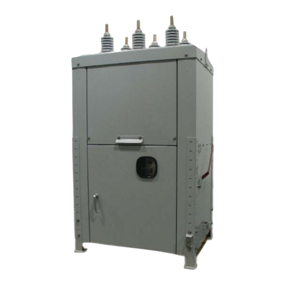
- Page 1 1VAL255101-MB Rev D (replaces IB 38-929M-15A) R-MAG Medium Voltage Outdoor Dead Tank Vacuum Magnetic Circuit Breaker Instruction Manual 15.5 kV 1250/2000/3000/3700 A 27 kV 1250/2000 A...
-
Page 2: Table Of Contents
R-MAG 15.5 kV Electrical Specifications ........ -
Page 3: Safety Notices
Figure 1. Hazardous Voltage Nameplate 1.0 SAFETY NOTICES Install the R-MAG circuit breaker within the design limitations as described on its nameplate and in these instructions. Follow your company’s safety procedures. This breaker should not be used by itself as the sole means of isolating a high voltage circuit. For... -
Page 4: Introduction
Storage) 3.2 Handling The R-MAG solid dielectric breaker comes with two brackets that attach to the sides of the cabi- net and provide provisions for lifting the breaker. A two-point lift is recommended using the loops in these brackets. (See Figure 2 Lifting Detail) -
Page 5: General Description
4.0 GENERAL DESCRIPTION 4.1 High-Voltage Assembly The high-voltage section of the R-MAG consists of three individual phase assemblies mounted on insulating standoffs. Each phase of the R-MAG consists of a single vacuum interrupter, flexi- ble shunt and operating rod. 4.2 Housing The doors of the breaker housing are removable and retained by hinge pins. -
Page 6: Standard Production Tests
4.5 Standard Control (ED2.0) The standard control package of the R-MAG is the ED2.0. The ED2.0 consists of a power supply, position indication and capacitor charging/discharging system. Refer to Appendix A for an overview of the ED2.0. -
Page 7: Operational Check Prior To Installation
6.2 Opening When the bottom coil is energized, the magnetic flux opposes the force generated by the magnet assembly. This reduces the holding force, the armature is released and the coil attracts the arma- ture to the bottom plate. Once there, it is held open by the magnet. 7.0 OPERATIONAL CHECK PRIOR TO INSTALLATION The breaker should be tested for mechanical and electrical operation before delivery to the installa- tion site. -
Page 8: Installation
8.3 Arrester Protection ABB recommends that surge arresters be properly applied in the substation. 8.4 Control Power Supply the control power as indicated on the wiring diagram. If 240 VAC is used, verify the con- nections for the heaters before applying power. -
Page 9: Inspection, Maintenance And Adjustment
9.0 INSPECTION, MAINTENANCE AND ADJUSTMENT The R-MAG circuit breaker is an extremely simple device and requires minimal maintenance, depending on the frequency of operation and local environmental conditions. The safety and successful functioning of any apparatus or system connected with the breaker largely depends on the proper and reliable operation of the unit. - Page 10 Any defective pole assembly must be replaced prior to the breaker being in service. 9.2 Replacement of Vacuum Interrupter Assemblies (See Figures 3-8) The following procedure is made with the R-MAG breaker in the open position, control power off and locked out, and stored energy capacitors discharged. CAUTION If power is removed from unit, and the Dip Switch I1004-1 is placed in the “on”...
- Page 11 7. Support the moving contact of the vacuum interrupter at the contact block (C) and loosen the nut (F) taking care not to apply any torque to the end of the vacuum interrupter as damage may result. (Figures 8). 8. With the stem nut loose (F), install the shoulder pin and washers through the triangular bell- cranks) to the bolt stem (B) (E) and fasten with the new locknut provided.
-
Page 12: Figure 3. Interrupter Assembly, 15.5 Kv, 1200 A
Figure 3. Interrupter Assembly 15.5 kV, 1250 A... -
Page 13: Figure 4. Interrupter Assembly 15.5 Kv, 2000 A
Figure 4. Interrupter Assembly 15.5 kV, 2000 A... -
Page 14: Figure 5. Interrupter Assembly, 15.5 Kv, 3000/3700 A
Figure 5. Interrupter Assembly 15.5 kV, 3000 A/3700 FA... -
Page 15: Figure 6. Interrupter Assembly 27 Kv, 1250 A
Figure 6. Interrupter Assembly 27 kV, 1250 A... -
Page 16: Figure 7. Interrupter Assembly 27 Kv, 2000 A
Figure 7. Interrupter Assembly 27 kV, 2000 A... -
Page 17: Figure 8. Contact Travel And Over-Travel Adjustment
Figure 8. Contact Travel and Over-Travel Adjustment 15.5 and 27 kV Figure 9. Trip Handle 15.5 and 27 kV... -
Page 18: Figure 10. Contact Erosion Graphs, 15.5 And 27 Kv
12.5 kA Interruption 16 kA Interruption 20 kA Interruption 25 kA Interruption Figure 10. 15.5 and 27 kV Contact Erosion Graphs... -
Page 19: Figure 11. High Voltage Cabinet Layout 15.5 And 27 Kv
Figure 11. High Voltage Cabinet Layout 15.5 and 27 kV... -
Page 20: Figure 12. Typical Schematic Diagram
Figure 12. Typical Schematic Diagram... -
Page 21: Figure 13. Standard Ed2.0 Circuit Board
Figure 13. Standard ED2.0 Circuit Board... -
Page 22: Figure 14. Typical Outline 15.5 Kv, 1200 A
Figure 14. Typical Outline 15.5 kV, 1250 A... -
Page 23: Figure 15. Typical Outline 15.5 Kv, 2000/3000/3700 A And 27 Kv, 1200/2000 A
Figure 15. Typical Outline 15.5 kV, 2000/3000/3700 A and 27 kV, 1250/2000 A... -
Page 24: R-Mag 15.5 Kv Electrical Specifications
10.0 15.5 kV R-MAG ELECTRICAL SPECIFICATIONS Rated Maximum Voltage 15.5 kV Voltage Range Factor, K Continuous Current (Ratings Available R1-R4) 600 A 800 A 1250 A 2000 A 3000 A 3700 FA Temperature Range -50°C to +55° C Dielectric Strength... -
Page 25: R-Mag 27 Kv Electrical Specifications
11.0 27 kV R-MAG ELECTRICAL SPECIFICATIONS Rated Maximum Voltage 27 kV Voltage Range Factor, K Continuous Current (Ratings Available R1-R4) 1250 A 2000 A Temperature Range -50°C to +55° C Dielectric Strength Low Frequency Withstand Dry 60 Hz 1 minute... - Page 26 CURRENT TRANSFORMER CONNECTIONS 600:5 MULTI-RATIO 1200:5 MULTI-RATIO CURRENT TRANSFORMER CURRENT TRANSFORMER TERMINAL RATIO TERMINAL RATIO X2-X3 50-5 X2-X3 100-5 X1-X2 100-5 X1-X1 200-5 X1-X3 150-5 X1-X3 300-5 X4-X5 200-5 X4-X5 400-5 X3-X4 250-5 X3-X4 500-5 X2-X4 300-5 X2-X4 600-5 X1-X4 400-5 X1-X4 800-5...
-
Page 27: Figure 16. Breaker Nameplate
ED2.0 BOARD VOLTAGE REQUIREMENTS CONTROL RANGE LOW VOLTAGE BOARD HIGH VOLTAGE BOARD BINARY INPUTS AC 20.4 VOLTS TO 264 VOLTS 20.4 VOLTS TO 264 VOLTS - KM1005 1, 2 OPENING COMMANDS CAN OPENING COMMANDS CAN (INCLUDES TRIP GO AS LOW AS 16.8 VAC GO AS LOW AS 16.8 VAC AND CLOSE) BINARY INPUTS DC... - Page 28 APPENDIX A INSTALLATION / MAINTENANCE INSTRUCTIONS R-MAG Medium Voltage Vacuum Power Circuit Breaker ED2.0 MAGNETIC ACTUATOR CONTROL BOARD...
- Page 29 Table Of Contents Description Page 1.0 OVERVIEW .............30 2.0 ED2.0 BOARDS AVAILABLE/MAGNETIC COIL ENERGIZING CAPACITOR .
-
Page 30: Overview
1.0 OVERVIEW The ED2.0 electronic control board is comprised of a Power Supply Recharge Unit, Control Unit, and FET Switching circuit which connects the Storage Unit Capacitors to the Magnetic Actuator coils. The power supply recharge circuitry adapts whatever input voltage, within the specified range (Section 2.0), is supplied to maintain an 80 V charge voltage across the capacitors. -
Page 31: Ed2.0 Boards Available/Magnetic Coil Energizing Capacitor
20 milliamperes. The input impedance (Z) is 300 kOhms except for binary inputs 1 and 2 (Remote open and close) which are around 14 kOhms input Z. There are seven different input channels. Only six of them are used for the R-MAG breaker (channel 5 is not used). -
Page 32: Protection Trip / Second Trip (Km1005 Pins 7 & 8)
3.4 Protection Trip / Second Trip (KM1005, CH 4, Pins 7 and 8) This input can be configured as either a Protection Trip or Second Trip function. It is programmed via Jumper JP1001 Pins 1 and 2 or as a normal input by jumpering JP1001 pins 2 and 3. The Protection Trip input is designed to work at a lower threshold of 7 VDC. -
Page 33: Binary Outputs
4.0 BINARY OUTPUTS Binary outputs are simply pairs of mechanical wipe relay contacts. They can be employed to switch in other circuitry or to an alarm indicator. See Illustration 3 and 4 for the power limitations of the contacts. Notice the flat curve for AC voltage in Illustration 4. On the inside of the low volt- age cabinet there is a membrane style button plate that contains a “Ready”... - Page 34 OUTPUT CONTACT SPECIFICATIONS: SEE ILLUSTRATION 2 FOR SPECIFIC LOADS AND VOLTAGES CHARACTERISTIC WIPE CONTACTS RELAY SWITCHING CHARACTERISTICS Maximum Switching Power 1500 VA on Resistive load Maximum Switching Voltage 400 VAC, 300 VDC Maximum Switching Current Maximum Rated Current CONTACTS CHARACTERISTICS Maximum On Resistance (Ron) 100 milliohms (measured by voltage drop 6 VDC 1 A)
-
Page 35: Features
Recharge Unit is 80% efficient. This means that the Auxiliary Power supply input must be at least 93.75 W for the 75 W setting or 41.3 W for the 33 W setting. The 33 W option is hardware selec- table with Jumper JP1019. 5.6 RS-232 Port / JTAG Communication Port Used by ABB factory only. -
Page 36: Power Considerations
6.0 POWER CONSIDERATIONS The ED2.0 power supply recharge unit adapts any voltage within the specified range of the board to maintain 80 V across the capacitors. The following voltage thresholds must be reached to complete the specified operations: 1. The capacitor voltage threshold for an Open operation is 49 volts. 2. -
Page 37: Capacitor Life
The ED2.0 board provides access through KM1003 for discharging the Storage Unit capacitors. Make sure the ED2.0 Control Board Power is removed before attempting to discharge the capac- itors. PROCEDURE: A 10 kOhm capacitor discharge resistor is mounted on the circuit board. Discharging is done by jumpering KM1003 pins 4 and 5. -
Page 38: Standard Ed2.0 Circuit Board And Connecting Diagram
7.0 STANDARD ED2.0 CIRCUIT BOARD AND CONNECTING DIAGRAM On filter card ILLUSTRATION 3 – ED2.0 CIRCUIT BOARD AND CONNECTIONS... -
Page 39: Default Jumper And Dip Switch Settings
8.0 DEFAULT JUMPER AND DIP SWITCH SETTINGS REV 02 AND GREATER ED2.0 Unless specified by the customer, the Low Energy and Under Voltage trip functions are disabled. Input three is set for Auxiliary trip mode as opposed to the Protection Relay trip mode. The Protection Relay mode has a lower switching threshold (12 V). -
Page 40: Troubleshooting Flowcharts
9.0 TROUBLESHOOTING FLOWCHARTS ILLUSTRATION 5 – READY LED CONTINUALLY FLASHING... - Page 41 ILLUSTRATION 6 – READY LED OFF...
- Page 42 ILLUSTRATION 7 – CB WILL EITHER NOT OPEN OR CLOSE...
-
Page 43: Instructions For Troubleshooting An Ed2.0 Control Board
10.0 INSTRUCTIONS FOR TROUBLESHOOTING AN ED2.0 CONTROL BOARD The Power Supply recharge circuitry either reduces (high voltage board) or increases (low volt- age board) input voltage within the specified range supplied to maintain an 80 V charge voltage across the capacitors. The Control Unit monitors binary inputs and outputs, hardware and software configurations, posi- tion sensors, capacitor charge, and switches the FET circuit to connect the capacitor voltage to the magnetic actuator coils following an open or close command. - Page 44 1. Use diagram on the previous page for references to troubleshooting the ED2.0 board 2. Disconnect source power to outdoor breaker 3. Warning: removing cover exposes live voltage 4. Remove the two #4 screws holding on the Push button plate and let it hang down 5.
- Page 45 SPECIFIC LINE ITEM CHECK IS SHOWN BELOW: PROBLEMS POSSIBLE CAUSES POSSIBLE SOLUTIONS The auxiliary supply Check pins 2 and 3 on KM1003 to confirm proper voltage is absent. input voltage is applied. The magnetic actuator Check the magnetic actuator circuit. Unplug the is damaged or not magnetic actuator from the plug to the left of the connected.
- Page 46 PROBLEMS POSSIBLE CAUSES POSSIBLE SOLUTIONS The circuit breaker is closed In this case, only the opening operation is available; and the close coil is open the circuit breaker (the ready LED will be disconnected or broken. turned off) and check the closing coil circuit. Unplug the magnetic actuator from the plug to the left of the mechanism (MA).
- Page 47 PROBLEMS POSSIBLE CAUSES POSSIBLE SOLUTIONS The closing coil is broken Check the closing coil circuit. Disconnect the mag- or damaged. netic actuator from the plug to the left of the mecha- nism. There are two Phillips head screws that keep the plug held together.
-
Page 48: Instructions For Changing Out An Ed2.0 Board
11.0 INSTRUCTIONS FOR CHANGING OUT AN ED2.0 CONTROL BOARD Warning: removing the cover exposes live voltage. 1. Disconnect the source power to the R-MAG. 2. Remove the two #4 screws holding on the Push button plate and let it hang down. - Page 49 7. Remove five plugs: KM1001, KM1002, KM1003, KM1004, KM1005, and KM1007. To remove, loosen hold down screws from each plug. 8. Remove plug for push button plate. This is not held by retainers. 9. Remove four .250-20 nut, lock and flat washer from the four corners. Keep the three rubber washers behind each screw.
-
Page 50: Notes
NOTES... - Page 51 NOTES...
- Page 52 ABB Inc. 655 Century Point Lake Mary, FL 32746 U.S.A. For sales & marketing contact your local representative or: Tel: +1-407-732-2000 1-800-929-7947 Fax: +1-407-732-2161 www.abb.com/mediumvoltage...
Need help?
Do you have a question about the R-MAG and is the answer not in the manual?
Questions and answers