Advertisement
Available languages
Available languages
Quick Links
RF TIMER SWITCH FOR
EN
JUNCTION BOX
INSTRUCTION'S MANUAL
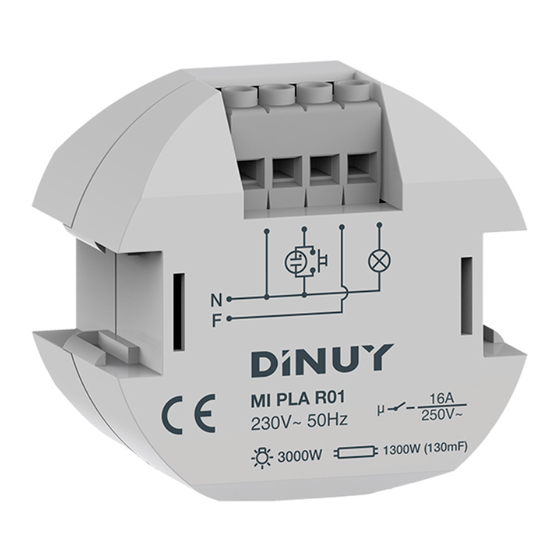
Technical features
Tracon code: MIPLAR01
Rated voltage: 230 V, 50 Hz
Switching capacity: 16 A, cosφ= 1
Incandescent lamps: 3.000 W
Fluorescent lamps: 1.300 W (130 μF)
CFL
: 18×7/12×11/10×15/10×20/10×23 W
Halogen lamps:
3.000 W
Own consumption: 40 mA
Time delay range: 30 mp - 10 p
Resetting: with new impulse
Detection range: 200 m in open field
Frequency: 868,4 MHz
Weight: 60 g
Operation temperature: -10 - +45 °C
Working temperature: -10 - +45 °C
Protection degree (housing): IP20 (EN 60529)
Relevant standard: EN 60669-2-1
CARACTERISTICS
Timer switch incorporating a radio frequency receiver that
means it can be triggered with a radio signal as well as with
wired push buttons.
It works with our movement detectors references
DM SEN R01, DM SEN R02 and DM SEN R03
with a maximum of 40 detectors.
The frequency used is 868,4 Mhz to avoid interference
problems. The signal is codified to be received only by the
required receivers.
Two hundred meters is the maximum distance to the
detectors in open field.
Illuminated push buttons: maximum 20 units.
Unlimited non illuminated push buttons.
Delay range adjustable with a potentiometer key from
30 seconds to 10 minutes.
INSTALLATION
This timer incorporates
an antenna which is
Antenna
needed to work properly
and it must not be
manipulated.
Pushbutton
* *
installation
an option
WORKING
Standard working function:
Once the timer is connected to the mains according to the installation
diagram shown on point number 2, this will close its contacts as
soon as it receives a correct RF signal or when a wired push button is
pressed. (Option).
The time will depend on the situation of the potentiometer key.
If any of the detectors has low battery power, the timer will indicate it by
making the connected load (lamps) blink at the end of the adjusted time.
Potentiometer
It allows to adjust the time between
30 seconds and 10 minutes.
Timer must be installed as shown in point
number 2 INSTALLATION. PUSH BUTTON.
PUSHBUTTON
CODIFYING THE DETECTORS
Once the timer is installed and helped by a pointed tool pressed
the indicated push button for 1 second. From this moment and for
30 seconds, the timer pass to the learning codes mode and it is
indicated by a short blink of the load (lamps).
Switch ON the detector to be codified by placing the ON/OFF
selector in ON position (according to the Instruction's manual in
the detector).
Once the code is learnt, the timer will confirm it by making the
load (lamps) blink.
Once this is done, please switch OFF the detector by placing
the ON/OFF selector in OFF position (according to the
Instruction's manual in the detector).
Repeat the same process with all the required detectors.
CLEARING DETECTOR'S CODES FROM TIMER'S MEMORY.
Helped by a pointed tool keep the push button pressed for 4
seconds. From this moment the timer enter into the clearing
codes mode. With this operation mode we clear from the
timer's memory all the detectors codes which it had in.
The memory is empty so the timer will recognise no signal
from any detector.
Once the timer finishes clearing all the codes it will indicate it
by making the load (lamps) blink twice and will return
automatically to the normal mode.
Once this is done, it will be necessary to codify all the required
detectors again.
POTENTIOMETER
Advertisement

Subscribe to Our Youtube Channel
Related Manuals for DINUY MIPLAR01


Summary of Contents for DINUY MIPLAR01
- Page 1 Technical features Once the timer is installed and helped by a pointed tool pressed Tracon code: MIPLAR01 the indicated push button for 1 second. From this moment and for 30 seconds, the timer pass to the learning codes mode and it is Rated voltage: 230 V, 50 Hz indicated by a short blink of the load (lamps).
- Page 2 AZ ADÓ- ÉS VEVŐEGYSÉGEK PÁROSÍTÁSA Műszaki adatok Az egység telepítése után a potenciométer mellett található Tracon kód: MIPLAR01 süllyesztett gombot egy másodpercig nyomva kell tartani. Ezután 30 másodpercig az egység tanuló módba vált, amit a vezérelt Névleges feszültség: 230 V, 50 Hz lámpa felvillanása jelez.
- Page 3 Spárovanie vysielačov a prijímača Technické údaje Po inštalácii prijímača je potrebné tlačidlo zapustené vedľa Tracon kód: MIPLAR01 potenciometra zatlačiť a podržať zatlačené po dobu 1 sekundy. Relé sa prepne do režimu spárovania na 30 sekúnd, čo Menovité napätie: 230 V, 50 Hz signalizuje aj zablikanie pripojeného svietidla.
- Page 4 SPOJITEV ODDAJNIKA IN SPREJEMNIKA Tehnični podatki Po vgradnji naprave pridržite za eno sekundo tipkalo, Tracon koda: MIPLAR01 ki se nahaja na napravi ugreznjeno poleg potenciometra. Za tem naprava za 30 sekund prestopi v način učenja, Nazivna napetost: 230 V, 50 Hz kar naznani utrip priklopljene luči.
-
Page 5: Uputstvo Za Upotrebu
SPARIVANJE DAVAČKIH I PRIJEMNIČKI MODULA Tehnički podaci Nakon instalisanja modula treba upušten taster pored potenciometra Tracon šifra: MIPLAR01 dr-žati pritisnuto do jedan sekund. Posle toga modul prelazi u režim učenja do 30 sekundi, a to signališe jedno šmiganje lampe upravljane. -
Page 6: Push Button
Tehničke karakteristike Nakon istalacije pritisnuti PUSH BUTTON na jednu sekundu. Nakon toga i slijedećih 30 s tajmer se nalazi u procesu učenja Tracon šifra: MIPLAR01 i žmiga ako su na izlazu spojene svjetiljke. Prebacite detektor Napajanje: 230 V, 50 Hz u ON na preklopki ON/OFF. - Page 7 Technické údaje funkčnost. Po instalaci přijímače je potřeba tlačítko zapuštěné vedle Tracon kód: MIPLAR01 potenciometru zatlačit a podržet zatlačené po dobu 1 Jmenovité napětí: 230 V, 50 Hz sekundy. Relé se přepne do režimu spárování na 30 sekund, signalizuje to i zablikání připojeného svítidla.
Need help?
Do you have a question about the MIPLAR01 and is the answer not in the manual?
Questions and answers