Table of Contents
Advertisement
Advertisement
Table of Contents

Related Manuals for Sauer Danfoss DH Series


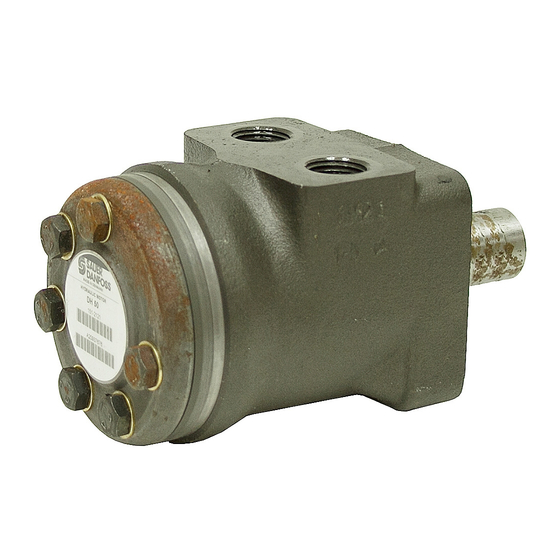
Summary of Contents for Sauer Danfoss DH Series
- Page 1 DH and DS Motors Assembly and Test Procedures...
- Page 2 DH and DS Motors Assembly and Test Procedures Revisions History of Revisions Table of Revisions Date Page Changed Rev. October 2011 edits to General Instructions October 2010 last new back page March 2010 last Fix Osaka address April 2009 First edition ©...
-
Page 3: Table Of Contents
DH and DS Motors Assembly and Test Procedures Contents Introduction Overview ................................4 General Instructions ............................4 Safety Precautions............................5 Unintended Machine Movement......................5 Flammable Cleaning Solvents......................5 Fluid Under Pressure..........................5 Personal Safety ............................5 Hazardous Material ..........................5 Tools Tools .................................. -
Page 4: Introduction
DH and DS Motors Assembly and Test Procedures Introduction Overview This manual includes information on assembly and testing of DH and DS Motors. To provide timely motor delivery when a customer places an order, you need to have all the necessary modules and equipment on hand. DH and DS motor assembly is based on a modular building concept. -
Page 5: Safety Precautions
DH and DS Motors Assembly and Test Procedures Introduction Safety Precautions Always consider safety precautions before beginning a service procedure. Protect yourself and others from injury.Take the following general precautions whenever servicing a hydraulic system. Unintended Machine Movement W Warning Unintended movement of the machine or mechanism may cause injury to the technician or bystanders.To protect against unintended movement, secure the machine or disable/ disconnect the mechanism while servicing. -
Page 6: Tools Tools
DH and DS Motors Assembly and Test Procedures Tools Tools Proper assembly of DH/DS motors requires these tools.You may use the dimensions and information in the drawings on the next page to fabricate them. Holding tool for motors with A2 flange (horseshoe) Holding tool for motors with C flange Fork tool 11065435 •... - Page 7 DH and DS Motors Assembly and Test Procedures Tools Tools (continued) Holding tool for motors with A2 flange (horseshoe) [7.125] 149.23 4X radius [5.875] 15.88 2.7 [0.5] 4X Ø 11/32 inch THRU [0.625] 3/8 UNC Tap Ø 12.7 [0.5] ± 0.254 [0.01] 2X Ø...
-
Page 8: Assembly Module Components
DH and DS Motors Assembly and Test Procedures Module Components Module Components The housing module and gear wheel set module ship in separate packages. Each module is packaged in a VCI plastic bag. Housing module Gear wheel set module Housing module sealed in plastic Gear wheel set module sealed in plastic Housing Module Quantity... -
Page 9: Motor Assembly
DH and DS Motors Assembly and Test Procedures Assembly Motor Assembly Position motor with shaft pointing down. Use A2 flange tool or C flange tool depending on your housing configuration. 1. Remove and discard the two temporary bolts that fasten the end cover. - Page 10 DH and DS Motors Assembly and Test Procedures Assembly Motor Assembly Ensure Proper Rotation (continued) You must install the internal gear wheel correctly in relation to the commutation of the spool valve to get proper rotation. 4. Install the spool shaft with a lower valve about 5 degrees clockwise from the center of the housing (as shown).
- Page 11 DH and DS Motors Assembly and Test Procedures Assembly Motor Assembly Install Distributor Plate (continued) 5. Mount the distributor plate on the housing and place the cardan shaft into the spool shaft On smaller displacements, be sure to place the end of the cardan shaft with the longest splines into the spool shaft.
- Page 12 DH and DS Motors Assembly and Test Procedures Assembly Motor Assembly Install End Cover (continued) 8. Grease an O-ring and place it in the O-ring groove on the top of the gear set. 9. Place the end cover over the gear set (Note orientation of end cover for DH models).
-
Page 13: Testing Testing Assembled Motor
DH and DS Motors Assembly and Test Procedures Testing Testing Assembled Motor Hydraulic Fluid Specifications General Testing Conditions Fluid type Mineral hydraulic oil class HM, ISO 6743/4 Viscosity range 35 ± 3 cSt 18/13 – contamination degree, ISO 4406 Oil cleanliness Rotation With the shaft pointing toward you and the system ports facing up, the motor must turn to the right (clockwise) when supplying pressure to the right connection port. - Page 14 DH and DS Motors Assembly and Test Procedures Testing Testing (continued) Test Data on DH Motors Maximum starting pressure (bar) Motor type 7 bar 10 bar DH 25 DH 32 DH 36 DH 40 DH 50 DH 60 DH 80 DH 100 DH 125 DH 160...
-
Page 15: Hydraulic Schematic
DH and DS Motors Assembly and Test Procedures Schematic Hydraulic Schematic The following schematic shows the proper connection of the motor to the hydraulic power unit for testing purposes. Note the position of the two pressure gauges. Position them as close as possible to the ports of the motor for the most accurate reading. -
Page 16: Motor Identification Motor Identification
DH and DS Motors Assembly and Test Procedures Motor Identification Motor Identification Fit a nameplate onto the end cover and stamp or etch the following data in the marked fields: Order nameplates separately. They are not included in the motor modules. Item Description Example... -
Page 17: Assembly Drawings Dh Exploded View
DH and DS Motors Assembly and Test Procedures Assembly Drawings DH Exploded View 11065435 • Rev AD • October 2011... -
Page 18: Ds Exploded View
DH and DS Motors Assembly and Test Procedures Assembly Drawings DS Exploded View 11065435 • Rev AD • October 2011... - Page 19 DH and DS Motors Assembly and Test Procedures Notes 11065435 • Rev AD • October 2011...
- Page 20 Products we o er: Sauer-Danfoss is a global manufacturer and supplier of high- quality hydraulic and electronic components. We specialize in • Bent Axis Motors providing state-of-the-art technology and solutions that excel in the harsh operating conditions of the mobile o -highway market. •...
Need help?
Do you have a question about the DH Series and is the answer not in the manual?
Questions and answers