Advertisement
MTP
WARRANTY
MTP Instruments warrants this instrument to
be free of defects in parts and workmanship for
INSTRUCTION MANUAL
one (1) year from date of shipment. This warranty
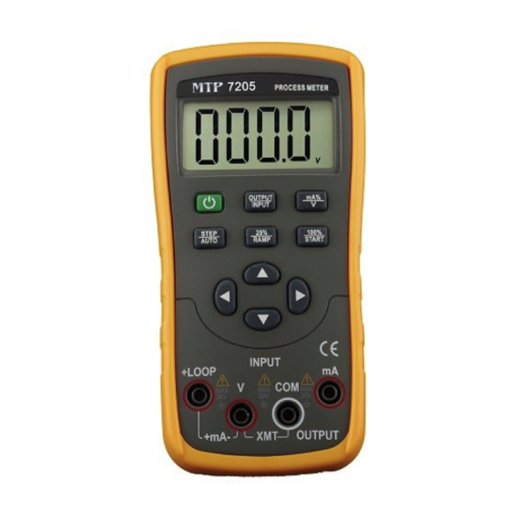
Loop Calibrator
does not apply to fuses, test leads and defects
Model MTP 7205
resulting from action of the user such as misuse,
improper wiring, operation outside of specification,
improper maintenance or repair, or unauthorized
modification.
MTP
Instruments
specifically
disclaims any implied warranties or merchantability
or fitness for a specific purpose and will not be held
liable for
any direct,
indirect,
incidental
or
consequential damages. MTP Instruments total
liability is limited to repair or replacement of the
product.
MTP Instruments Inc.
Advertisement

Related Manuals for MTP 7205


Summary of Contents for MTP 7205
- Page 1 WARRANTY MTP Instruments warrants this instrument to be free of defects in parts and workmanship for INSTRUCTION MANUAL one (1) year from date of shipment. This warranty Loop Calibrator does not apply to fuses, test leads and defects Model MTP 7205...
-
Page 2: Table Of Contents
Section One: Safety Information INDEX To ensure the safety operation, the following signs are used only as specified in this operation instruction: Page Safety Information………………………….…. 1 Warning A warning shows that if the operation Instrument Panel Layout and Functions….… 3 does not comply with the following Instrument Maintenance………………….….. - Page 3 To prevent the user and the Instrument from any electric Section Two: Instrument Panel Layout and shock and other hazards, it is necessary to observe the Functions following regulation: Warning • It is not allowed to operate the Instrument at the working field where there exists flammable gas or explosive gas or LCD display vapor.
- Page 4 Illustration of LCD Display Area 0 FS : When the symbol ‘O’ or ‘FS’ appears during the calibration, it denotes that the zero point or the full scale point is being calibrated. : When this symbol appears, it denotes that the battery is nearly used up and needs replacing.
-
Page 5: Instrument Maintenance
Section Three: Instrument Maintenance Replacing the Batteries This section provides some basic maintenance This Instrument is powered by two AA batteries procedures. Repair, calibration, and servicing not (IEC LR6). covered in this manual must be performed by Warning qualified personnel. For maintenance procedures not described in this manual, contact a Service To avoid electrical shock or personal injury: Center. - Page 6 Replacing Fuse Take off the protector of the Instrument; remove the battery cover by using a Warning standard-blade screwdriver to turn the To avoid personnel injury or damage to the battery door fasteners, and then take of meter, only specified fuse.
-
Page 7: Power-On/Off Of Instrument
operation should be carried out. Note To ensure correct operation of the Instrument, it is recommended to turn off the power pausing 5 seconds and then restart the Instrument. Automatic Power-off The factory default setting is that the Instrument will cut off the power automatically if no operation applied to the Instrument within 15 minutes. - Page 8 IN P U T + L O O P M A X M A X C O M M A X Output Operation Procedure 3 0 V 3 0 V 3 0 V + m A - X M T O U T P U T Function Display...
- Page 9 25% Step Current Output Press the key 〔100%/START〕and the symbols ‘ ’、‘’、‘0’、‘FS’ will appear in the Connect to the Instrument as shown in Figure display; 5-1; Press the key〔〕to be set to 100% and the When the key〔OUTPUT/IN〕is pressed, the current output will be 20mA.
- Page 10 type appears with‘ ’、‘ ’、‘ ’,in device as shown in the Figure 5-2: proper order. These symbols denote a low speed ramp high speed ramp I N P U T + L O O P respectively. The former is set to a cycle up to C O M M A X M A X...
-
Page 11: Instrument Measurement
Section Six: Instrument Measurement Input Operation Procedure Warning During the operation, never apply more than 30V Function between any two terminals, or between any terminal and Display Measurement Range Operation Operation earth ground. Any voltage more than 30V will not only do damage to the Instrument, but also lead to possible personal injury. - Page 12 Measuring DC Voltage IN P U T + L O O P C O M M A X M A X M A X 3 0 V 3 0 V 3 0 V Insert one end of the test lead into the V jack of the Instrument (INPUT)terminal and + m A - X M T...
-
Page 13: Setting Function
Providing 24V Power Supply for Measuring keys〔mA%/V〕and〔power〕simultaneously Loop Current power on, and release the〔mA%/V〕key only after the LCD displays all the contents. The Insert the test lead into the +LOOP and mA Instrument enters into the calibration mode, and input jacks of the input terminal (INPUT) of the the symbols ‘AP -XX ’appear in the LCD;... -
Page 14: Performance Index
Section Eight: Performance Index Output Performance Index (applicable to temperature range from 18℃ to 28℃, within one year after calibration) Output Range Output Range Resolution Accuracy Remark ±0.05% set value 20mA 0.001mA Max. load 1KΩat 20mA. 0.000~22.000mA ±4uA Max. load 1KΩat 20mA. Simu- ±0.05% set value Note:... -
Page 15: Caution
General Specifications Section Nine: Calibration - Power Supply: 21.5V alkaline batteries (LR6) - Battery Life: about 400mA/3V under the condition Note of 10mA with 1kΩ load Calibration: In order to keep the designed - Max. permitted Voltage: 30V(between any two accuracy of this Instrument, it is recommendable to terminals or between any terminal and earth calibrate your calibrator once a year. - Page 16 Selecting Standard Equipment Table 10-1 Standard Calibration Item Output Range Accuracy Recommended Equipment Digit meter:KEITHLEY 2000 Output DCA 20mA Digit meter MAX.22 mA ±(50ppm+0.4uA) Standard resistance:BZ10-100Ω Standard DCA 20mA MAX.33mA ±(100ppm+0.2uA) source Measure 5520 (FLUKE) or equivalent ment Standard DCV 28V MAX.33V ±(12ppm+15uV)...
- Page 17 Ambient Condition for Calibration Operating Output Calibration - Ambient temperature: 23°C ± 1°C; Operating calibration in order of items and - Relative humidity: 45 to 75% RH; calibration points listed in Table 10-2: Preheating: standard instrument should be preheated to specified time; this Instrument calibration...
- Page 18 Press the key 〔OUTPUT / INPUT〕to Press the key 〔STEP/AUTO〕and the LCD select output function , and the LCD displays displays ‘CAL 0 FS’. With the output ‘OUTPUT ’,‘mA ’; stabilized, repeat the operation of steps 5 Connect to the Instrument as shown in and 6;...
- Page 19 Operating Input Calibration calibration mode, and the symbols ‘CAL 0’ appear in the LCD. Operating calibration in order of items and Press the 〔OUTPUT / INPUT〕key to calibration points in Table 10-3: select measurement function , and the LCD displays ‘INPUT ’,‘mA ’; Table 10-3 Connect to the Instrument as shown in Item...
- Page 20 〔100%/START〕 key, and the LCD displays ‘SAVE ’, denoting that the calibrated N O R M A L A U X S C O P E point has been stored; Press the key〔STEP/AUTO〕and the LCD displays ‘CAL FS’ , and repeat the T R IG O U T operation of steps 5.
-
Page 21: Notice Of The Manual
Section Ten: Notice of the Manual Les Instruments The present operation instruction is subject Instruments to change without notice; The content of the operation instruction is Head Office regarded as correct. Whenever any user 4409, Charleroi street finds its mistakes, omission, etc., he or she Montreal-North, Quebec is requested to contact the manufacturer;...
Need help?
Do you have a question about the 7205 and is the answer not in the manual?
Questions and answers