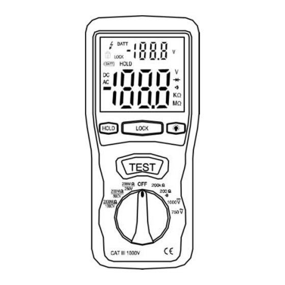
Summary of Contents for MTP MTP-4010
- Page 1 Instruction Manual DIGITAL INSULATION TESTER INSTRUCTION MANUAL Model MTP-4010 MTP Instruments...
-
Page 2: Safety Information
SAFETY INFORMATION Read the following safety information carefully before attempting to operate or service the meter. To avoid damages to the instrument, do not apply the signals which exceed the maximum limits shown in the technical specifications tables. ... - Page 3 testing acoustic continuity, disconnect circuit from main power supply and all loads from the circuit. Safety symbols: Caution, refer to this manual before using the meter. Dangerous voltages Meter is protected throughout by double insulation or reinforced insulation. When servicing, use only specified replacement parts.
-
Page 4: Specifications
1. SPECIFICATIONS 1-1 General Information Environment conditions: ①Installation Categories III ②Pollution Degree 2 ③Altitude up to 2000 meters ④Indoor use only ⑤Relatively humidity 80% max. ⑥Operation Ambient temperature: 0~40ºC Maintenance & Clearing: ①Repairs or servicing not covered in this manual should only be performed by qualified personnel. - Page 5 displayed. Low Battery Indication: The is displayed when the battery voltage drops below the operating voltage. Operating Temperature: 0ºC to 40ºC (32ºF to 104ºF) and Humidity below 80% RH Storage Temperature: -10ºC to 60ºC (14ºF to 140ºF) and Humidity below 70% RH Power source: DC9V (6x1.5V Size “AA”...
- Page 6 1-2 Electrical Specifications Accuracies are specified in the way: ±(…% of reading +…digits) at 23ºC±5ºC,below 80% RH. OHMS Range Resolution Accuracy Max. Overload open Protection Circuit Voltage 200Ω 0.1Ω +(1%+2) 4.5V 250Vrms 200kΩ 0.1kΩ 3.0V Continuity Beeper Range Resol Operation Max.open Overload ution...
- Page 7 DC Voltage Range Resolution Accuracy Input Overload Impedance Protection 1000V +(0.8%+3) 10MΩ 1000Vrms AC Voltage (40Hz~400Hz) Range Resolution Accuracy Input Overload Impedance Protection 750V +(1.2%+10) 10MΩ 750Vrms Meg OHMS Range Resolution Accuracy Terminal Voltage 200M 0.1MΩ 250V Ω/250V +(3%+5) +10%~-0% 200M 0.1MΩ...
-
Page 8: Parts And Controls
Range Test Current Short circuit current 200MΩ/250V 250KΩ(load) ≥1mA ≤1.5mA 200MΩ/500V 500 KΩ(load) 0~1000M 1MΩ Ω/1000V 1000~2000MΩ /1000V 2. PARTS & CONTROLS ① Digital Display ② Data Hold Button ③ Lock Button BATT BATT ④ Backlight Button Ω Ω ⑤ Test Button TEST 200k ⑥... -
Page 9: Battery Replacement
3. BATTERY REPLACEMENT 3-1 How to connect test leads. a). On MΩ Range: Connect the red test lead into the “ ” terminal and the black lead into the V Ω “COM” terminal. b) On 200Ω and ACV Range: Connect the red test lead into the “... -
Page 10: Insulation Resistance Measurements
4. INSULATION RESISTANCE MEASUREMENTS a). Measurements at 200M Ω /250V. This is the voltage used for the majority of insulation resistance tests on normal installation requirement. measure insulation resistance, press the test button to power on the tester. The LCD will display the insulation resistance. - Page 11 discharged automatically when the test button is released. Be careful not to turn the range switch knob while the test button is pressed, or the instrument will be damaged. b). Measurements at 2000MΩ/1000V Some specifications require testing at 1000V. This voltage must also be selected where the supply voltage of the installation is between 500V and 1000V.
-
Page 12: Ac/Dc Voltage Measurements
For hands free operation, a lock power on feature is incorporated on the press of the test button. Set LOCK button to lock test voltage. Pressing it again will turn the tester off. 5. LOW RESISTANCE (CONTINUITY) MEASUREMENTS a). Set the range switch to 200Ω.))) Position V Ω... -
Page 13: Power Tools And Small Appliances
to the circuit being measured. c) Read the voltage value on LCD. 7. POWER TOOLS AND SMALL APPLIANCES This test would also apply to other similar equipment that has a line cord. For double insulated power tools, the megohmmeter lead shown connected to the housing would be connected to some metal part of the tool (e.g. - Page 14 switch. If a weakness is indicated, the motor and other components should be checked individually. If the motor is disconnected at the motor terminals, connect one megohmmeter lead to the grounded motor housing and the other lead to one of the motor leads.
- Page 15 CABLES Disconnect the cable from the line. Also, disconnect opposite end to avoid errors due to leakage from other equipment. Check each conductor to ground lead sheath connecting megohmmeter lead to a ground and /or lead sheath and the other megohmmeter lead to each of the conductors in turn.
- Page 16 MTP Warranty MTP Instruments warrants this instrument to be free of defects in parts and workmanship for one (1) year from date of shipment. This warranty does not apply to defects resulting from action of the user such as misuse, improper wiring, operation...
- Page 17 Les Instruments Instruments Head Office 4409, Charleroi street Montreal-North, Quebec H1H 1T6 Telephone: (514) 326-7167 Fax: (514) 326-7835 Toll Free Number: 1-888-326-7167 Web Site: www.mtpinc.com E-Mail: info@mtpinc.com Distributed by:...


Need help?
Do you have a question about the MTP-4010 and is the answer not in the manual?
Questions and answers