Table of Contents
Advertisement
Operating instructions
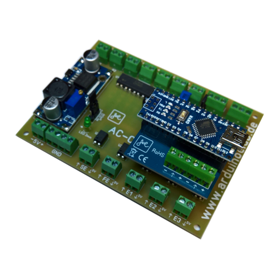
CNC Motion Controller: AC-CNC2017-2S (REV03)
Dear customer, thank you for choosing our product.
All our products are checked and subject to the controls of our
Quality assurance. We therefore guarantee that our products are free of
Defects in materials and workmanship.
Please read the safety instructions under 5.0 before you begin the work carefully.
Table of Contents :
www.arduinoclub.de
Advertisement
Table of Contents

Related Manuals for CNC AC-CNC2017-2S


Summary of Contents for CNC AC-CNC2017-2S
-
Page 1: Table Of Contents
Operating instructions CNC Motion Controller: AC-CNC2017-2S (REV03) Dear customer, thank you for choosing our product. All our products are checked and subject to the controls of our Quality assurance. We therefore guarantee that our products are free of Defects in materials and workmanship. -
Page 2: I Nstructions For Self-Builders
1.0 I nstructions for self-builders CNC Motion Controller: A C-CNC2017-2S (REV03) 1.1 You need Help? You have chosen a kit. If you have any concerns, we can also offer you the assembly of the components at this point in time. Just send us an email with your request to: ... -
Page 3: S Cope Of Delivery And Required Tool
2.1 S cope of delivery and required tool 2.1.1 Scope of delivery: ● 5 pieces o p tocoupler with 4 connections ● 1 p i ece o p tocoupler 1 6 connections ● 1 p i ece D C-DC Converter, set to +5V ●... - Page 4 2. Place all Optocoupler and the 16-legged optocoupler as in Figure 2.2.2 shown on the board and solder it. Figure 2.2.2 3. Now place all screw terminals as shown in Figure 2.2.3 on the board and solder them. Figure 2.2.3...
- Page 5 4. Now place the LED on the PCB, attention check the polarity, 5. the longer leg of the LED is the anode (+) and solder it. Figure 2.2.4 6. Now place the capacitor on the PCB, look the correct polarity, and solder it Figure 2.2.5...
- Page 6 7. Now plug the Arduino Nano with the socket onto the board and solder it. After soldering, please remove the Nano from the PCB! Figure 2.2.6 8. Place the precision potentiometer on the PCB as shown in Figure 2.2.7 and solder it. Figure 2.2.7...
- Page 7 9. Now solder the four one pin strips at the corner on the DC-DC converter. If you have a breadboard, you can do this to help you place the pins straight. If the solder are already soldered, you can proceed to step 9. Figure 2.2.8 10.
-
Page 8: Functional Test
Now insert the Arduino Nano into the CNC Motion Controller. Supply CNC Motion Controller with 24VDC (screw terminal "24V in"). In attention check the correct polarity. Connect the CNC Motion Controller to the computer using a USB cable. 3.2 S etting the EstlCam Software Settings in Estlcam : Open Estlcam and got to „Setup->CNC Controller“... -
Page 9: Programm The Cnc Motion Controller
● Pull up 5V: off See Figure 3.5.1 below. 3.3 Programm the CNC Motion Controller Programming the CNC motion controller card with the help of the Estlcam software Tap basic settings: Press the Button: „Programm Arduino“ 3.4 P reparation Tools: You need a voltage meter and a through tester or a corresponding instrument. -
Page 10: Inputs And Outputs
3.5 I nputs and outputs Test the inputs (SE, FE, E1, E2, E3): Open Estlcam and got to „Setup->CNC Controller->Inputs“ Figure 3.5.1 At the screw terminals, use the wire to bridge the limit switch 1, 2, 3; Sensor input and error input (E1, E2, E3, SE, FE). - Page 11 Test the Outputs (A1, A2): Open Estlcam and got to „Setup->View->CNC controller“ Check the Checkboxes, „Output 1“ and „Output 2“. Figure 3.5.3 Figure 3.5.4 If the outputs work properly, measure + 5v at the outputs.
- Page 12 LTV846 chip. At the output of the DC-DC converter, measure the + 5V. Figure 3.5.5 Additionally check all relevant solder connections. Testing the output (SpRel) for switching relays/milling spindles : Open Estlcam and got to „View->CNC Controller (F2)“ Figure 3.5.6...
-
Page 13: I Nverter And Hf Milling Spindle
3.6 I nverter and HF milling spindle Testing FOR/DCM: In the Estlcam Software: Open Estlcam and got to „View->CNC Controller (F2)“ In the window, press the "play" icon, the spindle is now turned on and the symbol now appears in red. (See figure 3.5.6) Check the passage from FOR to DCM, the red measuring line of your measuring device to FOR and the black to DCM. - Page 14 For problems, proceed as described in "Test the outputs (A1, A2)". Setting and testing from output 0-10v: In the Estlcam Software: Open „View->CNC Controller (F2)“. (See figure 3.5.9) Set the speed to the upper speed limit of your milling spindle e.g. 24000 rpm. Figure 3.5.9 Place a voltage meter at the output "0-10v".
- Page 15 Figure 3.5.11 Use a screwdriver to turn the adjusting screw of the precision potentiometer (next to the Arduino Nano) counterclockwise to increase the voltage or to reduce the voltage clockwise. Set the voltage to + 10.0 v. If you have any problems, make sure that the 24V connection is in fact 24V and that everything has been poled correctly.
-
Page 16: T Esting The Driver Ports
GND. If your oscilloscope only has one scanner, you can carry out the measurements sequentially. Figure 3.7.1 In the Estlcam Software: Open „View->CNC Controller (F2)“. Process the X axis. Figure 3.7.2 Depending on the direction in which you use X method, the measured values shown in... - Page 17 Step is a PWM signal and dir depending on the direction low (0v) or high (5v). Figure 3.7.3 As with the above connection pattern, you can test each axis. Of course you can also measure with a multimeter, but with an oscilloscope you can observe the interaction of the direction changes and methods of the axes better.
-
Page 18: S Tart-Up The Finished Control Card
4.0 S tart-up the finished control card The commissioning of the control card includes an interaction of electronic components and settings in the control software of your machine, here EstlCam. 4.1 L imit switches and Inductive sensors Figure 4.1.1 The control card allows the connection of one limit switch or inductive sensor at the X, Y and Z axes. - Page 19 In the Estlcam Software: Open „Setup->CNC Controller ->(Tap) Inputs“. Figure 4.1.3 Instead of the mechanical limit switches, you can also connect induction sensors that are operated with 5 volts. Figure 4.1.4 Connect the sensors and then measure the voltage that is connected to the E1-3 terminals, then you can adjust them up to 5v at the potentiometer of the DC-DC converter.
-
Page 20: S Tepper Motor Driver Module
4.2 S tepper Motor Driver Module Figure 4.2.3 The control card allows you to connect up to three stepper motor drivers. These connect your control card to the stepper motors, and supply them with electric power. The drivers regulate the direction and speed of the stepper motors. The stepper motor drivers are connected as follows: Version 1: Drivers are supplied with power supply for the motors. - Page 21 Variant 2: Drivers require a separate 5V power connection Figure 4.2.5...
-
Page 22: S Tepper Motors
4.3 S tepper Motors Figure 4.3.1 Stepper Motors Drive your machine with the help of threaded spindles or toothed belts. Here is a bi-polar motor version with 4 connections. Figure 4.3.2 The colours of the connecting cables on the stepper motors may differ depending on the manufacturer or model. -
Page 23: M Illing Motor, For Connection To 230Vac
4.4 M illing Motor, for connection to 230vac Figure 4.4.1 Here we are now dealing with milling motors whose speed is not from the control card is regulated. They usually have a AC power connection. Here is now a way to switch them on and off via the control card. Figure 4.4.2 Allow your milling to be connected by a skilled electrician, working on high power AC, are life-threatening! -
Page 24: F Requency Inverter And Hf Spindle
4.5 F requency inverter and HF spindle Figure 4.5.1 Connection example using a Huanyang HY01D523B frequency inverter. -
Page 25: S Ensor Input (Se) And Length Sensor/Touch Plate
4.6 S ensor input (SE) and length sensor/touch plate Figure 4.6.1 Through the execution of our control card it is possible to operate a tool length sensor, touch plate or a touch pen parallel. In the Estlcam Software: Open „Setup->CNC Controller->(Tap) Inputs“. Figure 4.6.2... - Page 26 If you want to use the sensor input, set it to active, inverted as shown in Figure 4.6.2. The following schematic shows the operation of a touch plate and a tool length sensor in parallel operation. Figure 4.6.3 As soon as the tool touches the tool length sensor or the touch plate, the The sensor input (SE) is switched on.
-
Page 27: Error Input (Fe)
Never use the error input as an emergency stop, the control card or the software could fail! In the Estlcam Software: Open „Setup->CNC ‘Controller->(Tap) Inputs“. Figure 4.7.1 Figure 4.7.2... -
Page 28: O Utputs A1, A2-Water Pump And Laser
Via the outputs 1 and 2 you have the possibility to switch devices such as coolant pumps or a laser, the application is as diverse as you have ideas. Open „View->CNC controller(F2)“. Turn on the checkboxes, "Output 1" and "Output 2". - Page 29 Figure 4.8.3 Use a solid state relay with zero crossing circuit, mechanical relays can cause interference.
-
Page 30: C Onnection To The Computer And Power Supply
DC current at the Screw terminal "24V in". Make sure that the polarity is correct. Use a high-quality stabilized power supply for operation. Our CNC control card requires approximately 350 mAh. For questions and suggestions, check out the www.arduinoclub.de. -
Page 31: S Afety Instructions
5.0 S afety Instructions 1. Read these operating instructions carefully before starting work. 2. Do not leave any components unattended, they can be swallowed by children or pets. 3. When soldering is done at very high temperatures, make sure that your workplace is free of combustible materials. -
Page 32: W Arranty And Guarantee
6.0 W arranty and Guarantee The legal warranty applies. Warranty for the kit We guarantee 6 months warranty on the kit. The guarantee includes the free repair of the defects, which are demonstrably due to the use of non-flawless material or manufacturing faults. Since we have no influence on the correct and proper construction, for understandable reasons we can only assume the guarantee of the completeness and perfect condition of the components.
Need help?
Do you have a question about the AC-CNC2017-2S and is the answer not in the manual?
Questions and answers