
Related Manuals for Antec DECADE Elite

Summary of Contents for Antec DECADE Elite
- Page 1 Antec Scientific Industrieweg 12 2382 NV Zoeterwoude The Netherlands DECADE Elite Service Manual 175.0020, Edition 3, 2018 T +31 71 5813333 info@AntecScientific.com www.AntecScientific.com...
- Page 2 (including electronic storage and retrieval or translation into a foreign language) without prior agreement and written consent from the copyright of the owner. Antec reserves the right to make changes to the design and specifications of the instrument and this manual without prior notice.
- Page 4 Declaration of conformity We Antec Leyden B.V., Zoeterwoude, The Netherlands, declare that the product: DECADE Elite™ Electrochemical Detector type 175 and 176 to which this declaration relates, is in conformity with the following CE directives: Low Voltage Directive (2014/35/EU) Safety requirements for electrical equipment for measurement, control, and laboratory use:...
-
Page 5: Intended Use
CHAPTER 1 Introduction Intended use The DECADE Elite Electrochemical Detector is used in combination with (Ultra) High Performance Liquid Chromatography for the electrochemical detection of suitable analytes in liquid samples. With this technique the amount of electroactive substances in mobile phase can be quantified. The... -
Page 6: Weee Directive
Else the protective and safety equipment of the device could fail. WEEE directive All equipment of Antec which are subjected to the WEEE directive shipped after August 13, 2005 are compliant with the WEEE marking requirements. Such products are labelled with the “crossed out wheelie”, depicted on the left site. -
Page 7: Table Of Contents
STEP 1 Export DECADE Elite calibration settings 27 STEP 2 Loading the EEPROM erase software 28 STEP 3 Formatting & test DECADE Elite memory 29 STEP 4 Uploading new FW update to the DECADE Elite 30 STEP 5 Import calibration settings 30 Trouble shooting 32... - Page 8 175.0020 - DECADE Elite service manual - rev 03 What to do if failed 44 PM Calibration DECADE Elite 45 Chapter 6 Sensor board installation 47 Contents of the kit 47 Preparation 47 Installation procedure 48 1. Removing the rear panel 49 2.
-
Page 9: Warning Symbols
CHAPTER 1 Introduction Warning Symbols The following symbols are used in this guide: This sign warns about the risk of electric shock. It calls attention to a procedure or practice which, if not adhered to, could result in loss of life by electrocution. Do not pro- ceed beyond a danger sign until the indicated conditions are fully understood and met. - Page 10 175.0020 - DECADE Elite service manual - rev 03 The attention sign signals relevant information. Read this information. The note sign signals additional information. It provides advice or a suggestion that may support you in using the equipment.
-
Page 11: Safety Instructions
Make sure power cords are connected to correct voltage sources: grounded AC power source, line voltage 100 – 240 VAC. The in- strument should be connected to a protective earth via a ground socket. The DECADE Elite must only be used with appliances and power sources... -
Page 12: Solvents
175.0020 - DECADE Elite service manual - rev 03 with proper protective grounding to prevent damage through build-up of static electricity. The power source should exhibit minimal power transients and fluctuations. If necessary connect to a filtered mains socket. USE ONLY WITH 250 V FUSES... -
Page 13: Biological Hazard
Always wear protective And gloves when handling toxic or biologically infectious samples to pre- vent bio hazards or hazards while working with the DECADE Elite. If nec- essary the instrument must be decontaminated before decommissioning or shipment of the instrument for repair to Antec or its representatives. - Page 14 175.0020 - DECADE Elite service manual - rev 03...
-
Page 15: Chapter 1 Introduction
PULSE mode. Furthermore, a Service, Diag(nostics) and Config(ura- tion) mode are available. In addition, crucial parameters can be controlled by relays and TTL. The DECADE Elite can support up to 3 flow cells (op- tional), which makes it possible to perform 3 independent measurements with one detector. -
Page 16: Instrument Description
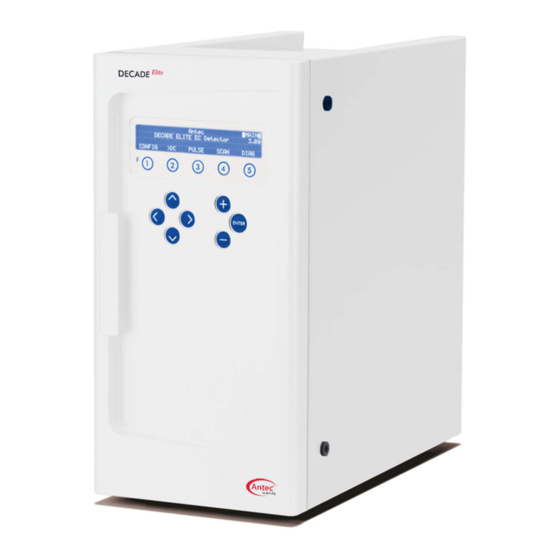
175.0020 - DECADE Elite service manual - rev 03 Instrument description DECADE Elite – Front side Description Description Instrument housing '+' and '-' value keys LC tubing inlet/outlet Cursor keys Instrument door panel Door handle (for opening door) 4 x 40 Ch LCD display Function keys <Enter>... -
Page 17: Decade Elite - Back Side
CHAPTER 1 Introduction DECADE Elite – Back side Description Description Instrument rear panel USB connector (USB B) Type label (pn, sn etc.) Fuse & power rating Digital I/O connector (25-pins sub-D fem) Mains switch/inlet Analog data (9-pins sub-D fem) Grounding stud... -
Page 18: Decade Elite - Oven Compartment
175.0020 - DECADE Elite service manual - rev 03 DECADE Elite – Oven compartment Description Description Cell cabinet Column clamp Cell connector (9-pins sub-D fem) Mounting hole for cell clamp (M4) Top fan heater (intake) Bottom fan heater (exhaust) Door sensor Mounting hole for column clamp (M3) Mounting plate (for cells &... -
Page 19: Chapter 2 Required Service Tools
CHAPTER 2 Required service tools C H A P T E R Required service tools The following tools are necessary for servicing the DECADE Elite/Lite: • Screwdriver • Socket wrench 3/16” • Phillips screwdriver PH-1 and PH-2 Figure 1, Screwdriver, socket wrench and Phillips PH-1 screwdriver (from left to right). - Page 20 (pn 250.0175) is shipped with the instrument. IO connection set Testing outputs is done using the factory supplied con- nector cable and screw terminal PCB: DECADE Elite I/O conn. Board (p/n 250.0131B) and DECADE Elite I/O cable 25M-25M, 1.8m (p/n 250.0131C).
-
Page 21: Chapter 3 Key Combinations For Service
Chapter 3 Key combinations for service C H A P T E R Key combinations for service Reset to factory defaults Function to bring the instrument into a predefined state with respect to op- erational parameters. In CONFIG screen press Enter button for more than 4 seconds. - Page 22 175.0020 - DECADE Elite service manual - rev 03...
-
Page 23: Chapter 4 Decade Elite Fw Upgrade
“.”, and the digit grouping symbol a comma “,”. Besides the Dialogue PC software a flash file containing the latest update of the DECADE Elite/Lite embedded software is necessary. Such a flash file has the following file name: DECADE_Elite_xxxx.anl. - Page 24 (connect the B plug of the cable into the USB port on the rear panel of the instrument. Figure 2 Left: rear panel DECADE Elite with USB cable connected (B type connector). Right: rear panel of the PC with USB cable connected (A type connector).
-
Page 25: Upgrading Firmware
Follow the instructions in this chapter accurately to successfully update the embedded software (FW) on your detector: • Switch on the DECADE Elite detector and start the Elite Dialogue software on your PC. The select devices menu will pop up. •... - Page 26 Importing the stored calibration settings into the DECADE Elite. Check if the Erase and FW file in the files section are correct. If not select the valid DECADE Elite ERASE and FW files (click on the ‘...’ button be- hind the file name box).
-
Page 27: Step 1 Export Decade Elite Calibration Settings
Each step will be explained in detail in the following paragraphs. STEP 1 Export DECADE Elite calibration settings By clicking the "Export calibration settings" button the DECADE Elite cali- bration settings will be saved to PC. The following instruction screen will pop-up. -
Page 28: Step 2 Loading The Eeprom Erase Software
STEP 2 Loading the EEPROM erase software The second step in the process is uploading the EEPROM erase software to the DECADE Elite. Start this step by pushing the button "Load EEPROM erase". The following instruction will pop-up:... -
Page 29: Step 3 Formatting & Test Decade Elite Memory
Make sure the detector is switched off and click Yes. • Switch on the detector and the Erase software will upload to the instrument automatically. STEP 3 Formatting & test DECADE Elite memory • Subsequently, the detector will reboot automatically and the erase software will start running. -
Page 30: Step 4 Uploading New Fw Update To The Decade Elite
175.0020 - DECADE Elite service manual - rev 03 STEP 4 Uploading new FW update to the DECADE Elite The fourth step in the process is uploading the new FW update to the DECADE Elite. • Start this step by pushing the button "Load new firmware". - Page 31 Chapter 4 DECADE Elite FW upgrade • Click “Yes” when the unit is fully started, only then it will automati- cally re-connect. In case of any problem, click “No”, switch off and on the unit and repeat this step (click button 5).
-
Page 32: Trouble Shooting
1 is repeated. If something goes wrong during or after the firmware upgrade, the DECADE Elite will not boot up correctly and will show the error message: E R R C h e c k s u m e r r o r In that case repeat the upload procedure as described in this chapter. -
Page 33: Chapter 5 Service Menu
This section describes the service menus accessible from keyboard/dis- play. It is primarily used for trouble shooting in case a calibration parame- ter is out of spec. For full calibration of the DECADE Elite/Lite the Elite Dia- logue software is required, please refer to document “171.0025 PM for DECADE and ROXY”. -
Page 34: Sett Menu
175.0020 - DECADE Elite service manual - rev 03 can be changed/selected by means of the ‘+’ and ‘-’ buttons on the key- board. SETT Menu F s a m p l e 5 0 H z t s l o c k... -
Page 35: Test Menu
Chapter 5 Service menu TEST Menu T E S T T e s t s P R E V M E M T E S T P R E V O U T P 1 2 = 1 P 1 4 = 1 P 1 7 = 1 P 2 0 = 1 P 2 3 = 1... -
Page 36: Out(Put) Test
PCB: DECADE Elite I/O conn. Board (p/n 250.0131B) DECADE Elite I/O cable 25M-25M, 1.8m (p/n 250.0131C) Figure 3 I/O connection set supplied with the DECADE Elite. Measure the output status of all individual outputs using a calibrated volt- meter: A. -
Page 37: In(Put) Test
Chapter 5 Service menu need to be tested. Common: pin 3 and 6, Normally closed: 1 and 4. See schematic drawing below. Table II. Outputs on digital IO connector Description RELAY 1 (normally closed) RELAY 1 (normally open) RELAY 1 (common) RELAY 2 (normally closed) RELAY 2 (normally open) RELAY 2 (common) -
Page 38: Mem(Ory) Test
WRITE/READ action. In case the test was unsuccessful please contact your Antec representative for further advise. RC filter test This is a test specifically for internal USE at the Antec factory only. It is not used for diagnostic purposes in the field. -
Page 39: Adj(Ustments) Menu
Chapter 5 Service menu ADJ(ustments) menu A d j u s t m e n t s P R E V Z E R . O U T P E C E L L T E M P = - 0 . 0 6 8 n A Z E R . -
Page 40: Zer.ie Zero Current For Ie Converters
175.0020 - DECADE Elite service manual - rev 03 ZER.IE zero current for IE converters Before adjusting the zero current make sure the system has been stabi- lized for more than an hour with the cell off and T=35 Cell cable must be disconnected all the time. If the cell cable is connected ‘ERR 13 Disconnect flow cell’. -
Page 41: Outp Output Voltage
Chapter 5 Service menu OUTP Output voltage Before adjusting the output voltage make sure the system has been stabi- lized for more than an hour with the cell off and T=35 C. Cell cable must be disconnected all the time. O U T P O u t p u t = + 1 . -
Page 42: Ecell Cell Potential
175.0020 - DECADE Elite service manual - rev 03 ECELL Cell potential Before adjusting the cell potential make sure the system has been stabi- lised for more than an hour with the cell off and T=35 E c e l l = + 4 . 9 0 V... -
Page 43: Temp Temperature Calibration
Chapter 5 Service menu TEMP Temperature calibration The DECADE Elite heater is controlled by a LM-35 temperature sensor lo- cated in the heater compartment behind the cell cabinet. The temperature sensor can be calibrated using the procedure described below. The tem- perature is calibrated at the center of the oven compartment where the flow cell is located. -
Page 44: What To Do If Failed
175.0020 - DECADE Elite service manual - rev 03 3. Make sure set temperature (set point) is 45 C, if not, set temperature using +/- and wait an hour to stabilize. 4. After one hour read the temperature of the external calibrated temp... -
Page 45: Pm Calibration Decade Elite
Chapter 5 Service menu PM Calibration DECADE Elite Full calibration of all DECADE Elite parameters is done using an auto- mated calibration script in Elite Dialogue software. This procedure is de- scribed in document 171.0025 PM for DECADE and ROXY. - Page 46 175.0020 - DECADE Elite service manual - rev 03...
-
Page 47: Chapter 6 Sensor Board Installation
This section describes the installation of an additional channel (sensor board) in a DECADE Elite using the DECADE Elite additional channel kit (p/n 175.0210). This kit enable you to upgrade your DECADE Elite to an instrument with two or three flow cells. -
Page 48: Installation Procedure
Therefore, always disconnect the instrument from all power sources before disassembly. In the next sections all steps are explained in detail to guide you through the installation procedure. In case of questions please contact Antec, the Netherlands for assistance. -
Page 49: Removing The Rear Panel
Sensor board installation 1. Removing the rear panel To be able to access the electronic parts in the DECADE Elite the rear panel has to be removed. All circuit boards are mounted on a separate metal frame, which is fixed on the rear panel of the detector. To access the electronic parts loosen the four M3 Phillips screws as depicted in the figure below using a Phillips PH-1 screw driver. -
Page 50: Disconnecting Internal Wiring
175.0020 - DECADE Elite service manual - rev 03 Figure 7 Detector with rear panel pulled backwards and frame with elec- tronic boards accessible. The rear panel is constrained by the length of the connected cables. The PCB frame can rest on the casing of the power supply compartment with- out any problem (as depicted in the figure above). - Page 51 Chapter 6 Sensor board installation Figure 8 Detector with all cables disconnected from the control board. In- sert (top-left side): cable clamp. Red arrow depicts how to open the clamp. See the photographs on the next page how to disconnect the internal cell cable from the electronics: •...
- Page 52 175.0020 - DECADE Elite service manual - rev 03 Figure 9 Top-left: Move PCB frame backwards to access the internal cell cable connection on sensor board 1. Top-middle: remove internal cell ca- ble from the cable clamp. Top-right: loosen the 2 hex screws fixing the in- ternal cell cable to the sensor board connector and disconnect the cable.
-
Page 53: Removing Emc Enclosure
Chapter 6 Sensor board installation 3. Removing EMC enclosure To remove the EMC enclosure perform the following steps: • Loosen and remove the hex screws fixing the sensor board con- nector to the EMC enclosure using the 3/16” socket wrench. •... -
Page 54: Mounting Additional Sensor Board
175.0020 - DECADE Elite service manual - rev 03 4. Mounting additional sensor board To mount an additional sensor board perform the following steps: • Remove the two hex screws from the new sensor board supplied in the kit using the 3/16” socket wrench. - Page 55 Chapter 6 Sensor board installation Figure 12 Remove the black plastic connector cover strip by bending the retaining clips outwards with a tweezer or pointed metal object and shove the complete metal plate of the plastic pin. Figure 13 Control board with 2 sensor boards under the EMC enclosure. Proceed to the next section describing the installation of an additional in- ternal cell cable.
-
Page 56: Opening The Cell Cabinet
175.0020 - DECADE Elite service manual - rev 03 5. Opening the cell cabinet To access the electronics compartment from the front side of the detector (to install an additional internal cell cable) follow the steps described be- low: •... - Page 57 Chapter 6 Sensor board installation • Open the detector electronics compartment from the front side by pulling the detector cell cabinet out of the housing from the top side. Pivot the bottom side of the cell cabinet until the top side of the isolated heater compartment is obstructed by the top panel of the detector.
-
Page 58: Installation Of Internal Cell Cable
175.0020 - DECADE Elite service manual - rev 03 6. Installation of internal cell cable • Remove the plastic cover strip from the cell connector opening (sensor 2) in the cell cabinet (top-left side) using a tweezer or other pointed metal object. Bend the metal retaining clips outwards to be able to shove them from the plastic fixing pins (see photo on the previous page). -
Page 59: Reconnecting Wiring & Mounting Rear Panel
Chapter 6 Sensor board installation 7. Reconnecting wiring & mounting rear panel Follow the steps below to reassemble the instrument: • Fix the two (or three) connectors of the internal cell cables into the corresponding sensor board connectors using hex screws with two plastic washers as depicted in the photo below. - Page 60 Check and calibrate the instrument as described in Chapter 4 (ei- ther via the SERVICE menu or using the PM procedure). Perform a dummy cell test as described in the DECADE Elite IQ/OQ/PQ manual (document 171.0023) to check if the instrument performs within specification with respect to cell current and noise.
-
Page 61: Chapter 7 61 Replacing The Power Supply
Replacing the power supply C H A P T E R Replacing the power supply This section describes the replacement of the DECADE Elite power supply (PSU), p/n 175.0630. For this service action the following tools are re- quired: •... - Page 62 175.0020 - DECADE Elite service manual - rev 03 Take care, the PSU frame has reasonably sharp edges. Do not put any tension on the electronic wiring connected to the PSU, it may lead to damage and malfunction of the detector.
-
Page 63: Disconnecting The Psu Wiring
CHAPTER 7 Replacing the power supply Disconnecting the PSU wiring Follow the steps below to disconnect the wiring: • Pull the PSU frame out of the bottom panel as far as possible to be able to access the screws fixing the wiring. •... - Page 64 175.0020 - DECADE Elite service manual - rev 03 Figure 21. PSU wiring of the primary and secondary power circuitry. Table IX. Lay-out of the PSU wiring. Symbol on PSU Wire color Description Brown Line Blue Neutral Green/yel- Protective ground...
-
Page 65: Replacement Of Psu
CHAPTER 7 Replacing the power supply Replacement of PSU To replace the PSU on the PSU frame follow the steps below: • Remove the PSU frame with PSU completely out of the bottom panel and lay it flat on the table. •... - Page 66 175.0020 - DECADE Elite service manual - rev 03 Figure 23. The PSU fan outlet should be facing downwards and positioned on top of the corresponding ventilation holes in the PSU frame. • Place the new PSU with the PSU fan outlet facing downwards on top of the corresponding ventilation holes in the PSU frame.
-
Page 67: Reinstallation Of Psu Frame
Elite or DataApex Clarity software. In case the instrument does not start up correctly (Elite) or does not com- municate over LAN/USB (Lite), check if all steps in this chapter are exe- cuted correctly. If the problem persists please contact Antec for advice. - Page 68 175.0020 - DECADE Elite service manual - rev 03...
-
Page 69: Chapter 8 Specifications Decade Elite
2.5 AT / 250V, 5x20 mm, IEC 60127-2 For safety reasons, any other internal fuse or circuit breaker is not operator accessible, and should be replaced only by Antec authorized personnel. Use only manufacturer-supplied fuses. For optimum analytical performance it is recommended that the ambient temperature of the laboratory be between 17-25 °C and be held... -
Page 70: General
175.0020 - DECADE Elite service manual - rev 03 General Operating modes DC, PULSE SCAN (Lite: DC mode only) Other mode CONFIG, DIAG and SERVICE Sensors Up to 3 flow cells (Lite: single cell only) Autozero triggered by keyboard, rear panel TTL, or re- mote PC control (LAN) Max. -
Page 71: Pulse Mode
CHAPTER 8 Specifications DECADE Elite PULSE mode Range 10 nA - 200 µA in 1, 2, 5 increments Filter (ADF) 0.5 - 0.001 Hz in 1, 2, 5 increments OFF: for unprocessed data Potential (Ec) -2.50 V to + 2.50 V with 10 mV increments... - Page 72 175.0020 - DECADE Elite service manual - rev 03...