Table of Contents
Advertisement
Quick Links
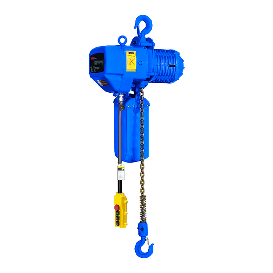
ELECTRIC CHAIN HOIST (Single Brake)
OPERATION MANUAL
This operation manual is intended as an instruction manual for
trained personnel who oversee installation, maintenance, repair
etc.
Before equipment use, please read this operation manual
ELECTRIC CHAIN HOISTS (Single Brake)
Model NECH
ACI Hoist & Crane | 2721 NE 4th Ave Pompano FL 33064 | 954.367.6116
Serial Number:
Date Purchased:
Scan QR Code with
SmartPhone to view our website.
Advertisement
Table of Contents

Related Manuals for ACI Hoist & Crane NECH Series


Summary of Contents for ACI Hoist & Crane NECH Series
- Page 1 ELECTRIC CHAIN HOIST (Single Brake) OPERATION MANUAL This operation manual is intended as an instruction manual for trained personnel who oversee installation, maintenance, repair etc. Before equipment use, please read this operation manual Serial Number: Date Purchased: ELECTRIC CHAIN HOISTS (Single Brake) Model NECH ACI Hoist &...
- Page 2 Electric Chain Hoists (Single Brake) PAGE: 2 Model NECH NECH-0214 ACI Hoist & Crane | 2721 NE 4th Ave Pompano Beach, FL 33064| 954.367.6116 Visit WWW.ACIHOIST.COM for the most current information...
-
Page 3: Table Of Contents
TABLE OF CONTENTS 1.0 WARRANTY ................................5 2.0 SAFETY PRECAUTIONS............................6 2.1 Safety Alert Symbols ..............................6 2.2 Important Information and Warnings ........................7 2.3 Safe Hoisting and OSHA Compliance ......................... 8 2.4 Warning Tags and Labels ..........................10 2.5 General Safe Operation Requirements ......................11 3.0 GENERAL DESCRIPTION &... - Page 4 6.8 Trolley Inspection ............................... 42 6.9 Tests ................................... 44 6.9.1 Operational Test ..........................44 6.9.2 Load Test ............................46 7.0 MAINTENANCE & REPAIR ............................47 7.1 Lubrication ................................. 47 7.1.1 Hoist Gear Housing ..........................47 7.1.2 Hook Thrust Bearing ........................... 48 7.1.3 Chain Lubrication ..........................
-
Page 5: Warranty
1.0 WARRANTY Every product is thoroughly inspected and tested before it is shipped from the factory. If any problem develops within one year, return the product prepaid to the factory. If an inspection reveals that the problem is caused by defective workmanship or material, repairs will be made without charge and the product will be returned with the shipping prepaid. -
Page 6: Safety Precautions
2.0 SAFETY PRECAUTIONS 2.1 Safety Alert Symbols Throughout this manual are steps and procedures that can prevent hazardous situations, the following symbols are used to identify the degree or level of hazard seriousness. DANGER, WARNING AND CAUTION NOTICE Symbol Description Danger Indicates an imminently hazardous situation which, if not avoided, will result in death or serious injury and property damage. -
Page 7: Important Information And Warnings
It is the responsibility of the owner/user to install, inspect, test, maintain, and operate a hoist in accordance with ASME B30.16, Safety Standard for Overhead Hoists, OSHA Regulations, and ANSI/NFPA 70, National Electrical Code. If the hoist is installed as part of a total lifting system, such as an overhead crane or monorail, it is also the responsibility of the owner/user to comply with the applicable ASME B30 volume that addresses that type of equipment used in the system. -
Page 8: Safe Hoisting And Osha Compliance
• Modifications to upgrade, rerate, or otherwise alter this equipment shall be authorized only by the original equipment manufacturer or qualified professional engineer. Equipment described in this manual may be used in the design and manufacture of cranes or monorails. Additional equipment or devices may be required for the crane or monorail to comply with applicable crane design and safety standards. - Page 9 4. Daily Inspections: Many items must be checked on a daily basis. Written records do not need to be kept for these inspections (OSHA 1910.179 j 1; ANSI B30.16). • ACI provides operator-training classes to perform these inspections. These quick inspections are completed to verify the unit is safe to use prior to daily operation.
-
Page 10: Warning Tags And Labels
2.4 Warning Tags and Labels The warning tag illustrated below is supplied with each hoist shipped from the factory. If the tag is not attached to your hoist’s pendant cord, call ACI Hoist & Crane immediately to receive it and install it. Read and obey all warnings attached to this hoist. -
Page 11: General Safe Operation Requirements
2.5 General Safe Operation Requirements Before installing, removing, inspecting, or performing any maintenance on a hoist, the main switch shall be de-energized. Lock and tag the main switch in the de-energized position in accordance with ANSI Z244.1. Follow other maintenance procedures outlined in the manual and applicable ASME B30 volumes. Additional WARNINGS are listed in various portions of this manual. -
Page 12: General Description & Features
3.0 GENERAL DESCRIPTION & FEATURES 3.1 Model Numbering NECH Type Hoist Speed (FPM) NECH = Electric Chain Trolley Speed Capacity V = Variable Lift (ft.) Suspension Leave Empty for 005 = ¼ Ton 10 = 10 ft. H = Hook Mounted Single Speed 010 = ½... -
Page 13: Pendant Control
3.2 Pendant Control Pendant stations are provided fully assembled. When using a pendant control, depress the up button to raise the hoist or the down button to lower the hoist as shown in Figure 3.5.1 below. To stop motion, release the buttons. Ensure the motor comes to a complete stop before reversing the direction. - Page 14 Push Button Station Dimensions Table 3.2.2 Electric Chain Hoists (Single Brake) PAGE: 14 Model NECH NECH-0214 ACI Hoist & Crane | 2721 NE 4th Ave Pompano Beach, FL 33064| 954.367.6116 Visit WWW.ACIHOIST.COM for the most current information...
-
Page 15: Installation
4.0 INSTALLATION ACI electric hoists are lubricated and tested before being shipped from the factory. To place a hoist in service, install the hoist onto a beam by adjusting the hoist appropriately for the flange width. Then connect it to an electrical service and perform pre-operation tests, checks and inspections. -
Page 16: Installation Of Hoist
• If personnel are required to work at elevations in excess of 6 feet above floor or ground level, a fall prevention policy and procedure shall be developed, documented, and implemented prior to installation. • Check power supply that will be furnished to the hoist and trolley. It must be the same as shown on the hoist and trolley serial plate. -
Page 17: Installation Of Hoist With Trolley
4.2.1 Installation of Hoist with Trolley If the trolley hoist is mounted on a skid, do not remove it immediately. The skid will hold the trolley hoist unit in an upright position until assembled on the crane or monorail. Figure 4.2.1.1 Side Plate S Side Plate G Spacer Pin... - Page 18 Figure 4.2.1.3 Figure 4.2.1.4 2. Measure the flange width of the beam where the trolley is to be installed. 3. Slide one stack of inner adjusting spacer over the suspension shaft. Total width should be about half of the flange width of the beam. Then insert suspension shaft into suspender T (refer to Figure 4.2.1.5). Suspender Shaft Suspender T...
- Page 19 Adjusting Spacers Figure 4.2.1.6 5. Secure the shaft with spacer pin and cotter pin. 6. Refer to Figure 4.2.1.7 for adjusting the width of the trolley by installing inner and outer adjusting spacers on the suspension shaft. Figure 4.2.1.7 7. Make sure both side plates are spread fully outward and measure dimension “A”. Dimension “A” must be 5/32” (4 mm) greater than “B”...
-
Page 20: Installation Of Trolley Hoist On The Beam
4.2.2 Installation of Trolley Hoist on the Beam 1. Place trolley hoist in correct position relative to bridge beam or monorail, orienting it for proper end approach in accordance with specification requirements. Be sure that collectors and conductors are properly positioned and aligned. -
Page 21: Connecting Power Supply To Hoist
4.2.3 Connecting Power Supply to Hoist Disconnect power and lockout and tag the power before connecting the power supply to the hoist to prevent accidental application of power. Only a qualified person should connect the power supply to the hoist. Check the power supply that will be connected to the hoist to ensure that it is the same voltage as shown on the hoist serial number plate. - Page 22 Figure 4.2.4.2 At this time the chain container should be installed utilizing the following procedures: 1. Lower hoist hook until lower limit switch stops downward motion of hook. 2. Place container on hoist and secure it in place with the chain container pins and cotter pins. Orient the container as shown in Figure 4.2.4.3.
-
Page 23: Prior To Operation
4.3 Prior To Operation • Before energizing the power supply, and inspecting and testing the hoist prior to initial operational use, check that all electrical connections are in accordance with the wiring diagram. • ASME B30.16 requires that all new, altered, or modified hoists be inspected by a designated person prior to initial use to verify that the equipment and installation comply with applicable provisions of the standard. -
Page 24: Trolley Motor Phasing
3. Interchange any two lines supplying power to the hoist. 4. Re-energize power supply to the hoist. 5. Check the hoist travel direction for correct hook motion by pressing UP on the hoist control device. If the direction of the hook travel matches the direction marking of the hoist control device button activated then the hoist motor is properly phased. -
Page 25: Hoist Load Test
2. If the hoist has a trolley, operate the trolley without a load on the hoist hook for the entire travel distance of the trolley to ensure that the trolley, hoist, load block and hook do not interfere with any other items or pieces of equipment located in the travel path. -
Page 26: Operation
5.0 OPERATION The operator of the hoist must be well acquainted with this manual and be instructed on the requirements for safe operation. The operator’s clothing should be in accordance with working conditions. The operator should always have at hand the operation manual or a copy of the Operation and Safety sections, which must be placed near power circuit breaker or on an easy and accessible place. -
Page 27: General Do's And Do Not's
• The operator shall know hand signals used for hoist and crane operations, if a signalperson is used in the operation, and accept signals of only persons authorized to give hand signals EXCEPT to obey a stop signal regardless of who gives it. -
Page 28: Safety Rules For Operating The Hoist
• Only attach a load to the hoist hook that does NOT exceed the rated load capacity of the hoist. • Confirm that the size of the attachment of the sling or other lifting device to be used is compatible to the size of the hoist hook. -
Page 29: Safety Rules Before Each Shift
• Block loads before landing if slings or other lifting devices must be removed from under the landed load. • Exercise care when removing a sling from under a landed and blocked load. • DO NOT leave a suspended load unattended unless specific precautions to prevent the load from inadvertently lowering have been instituted and are in place. -
Page 30: Inspection
6.0 INSPECTION All ACI hoists are inspected and tested at the factory. Regular in-service inspection and preventative maintenance programs not only help reduce overall maintenance costs but may also prevent service shutdowns by forewarning of problems that could arise and cause a shutdown. Regular inspections, periodic minor adjustments, regular cleaning, lubrication, and replacement of worn parts can help maintain the hoists performance and operation in good order. -
Page 31: Inspection Records
• Warning signs and barriers shall be utilized on the floor beneath the hoist, crane or lifting system where overhead maintenance, repair or inspection work creates a hazardous area on the floor beneath the hoist, crane or lifting system. • If the crane runway or monorail remains energized because other hoists or cranes are on the same runway or monorail are in operation, rail stops or a signal person(s) shall be located full-time at a visual vantage point for observing the approach of an active hoist(s) or an active crane(s) to prohibit contact by the active hoist(s) or... -
Page 32: Daily, Frequent & Periodic Inspections
must be increased if hoist is subjected to severe atmospheric environmental conditions, such as corrosive vapors, extreme heat or cold, cement or dust and other airborne contaminants. The user should carefully consider all environmental conditions and adjust frequency and degree of maintenance for his/her local conditions. Various codes also regulate inspection and maintenance programs. - Page 33 If any damage or malfunctions are noted by the daily inspection items of Table 6.3.1, the operator shall not operate the hoist and shall immediately advice the supervisor so corrective action may be taken. If the hoist is tagged with an out of order sign, the operator shall not operate the hoist. Hoist operators should be trained to be aware of malfunctions of the equipment during operation, and to immediately stop operation if such malfunctions occur and to immediately advice the supervisor so corrective action may be taken.
-
Page 34: Hook Inspection
Check that the load chain is properly seated Replace. in the reeving/parting and that the load Reeving/Parting chain and associated parts are not twisted around each other. Check that the capacity, warning and other Replace. Capacity & Warning safety labels are not missing and are Label legible. - Page 35 Figure 6.4.1 Table 6.4.1 Hook Dimension Reference Hook Dimensions Capacity* 0.25 1.02 0.75 1.02 0.75 1.34 0.94 0.94 1.65 1.18 1.81 1.22 1.69 1.18 1.93 1.57 1.42 1.97 1.42 2.32 1.89 2.64 1.61 2.24 1.61 2.36 1.89 3.43 2.36 3.31 2.36 3.35 2.76...
-
Page 36: Limit Switch Inspection
Never weld handles or other attachments to the hook. Heat applied to the hook will alter the original heat treatment of the hook material and reduce the strength of the hook; if handles or other attachments are required on the hook, contact ACI or the distributor of the hoist. DO NOT use cotter pins, groove pins or locknuts that have been removed during disassembly. - Page 37 Limit Lever Limit Actuator (Limit Spring) Rocker Arm Figure 6.5.2 When the lowest position is reached the limit actuator on the tail end of the load chain trips the limit lever (see Figure 6.5.3). Limit Lever Limit Actuator (Limit Spring) Rocker Arm Figure 6.5.3 The limit lever is connected to a limit switch that automatically stops the hoist motor.
- Page 38 Figure 6.5.4 Install the stopper as follow: • In some hoist models even when the chain container is used, the free end of the chain is attached to the hoist body as shown in Figure 6.5.5. Depending on the hoist size and capacity, install the chain stopper approximately 7 to 12 links from the free end and make sure the chain remains free of twists.
-
Page 39: Load Chain Inspection
Chain Spring Stopper Figure 6.5.6 6.6 Load Chain Inspection Load chain on hoists in regular service should be visually inspected daily by the operator. If the hoist is used in multiple shift operations, the load chain should be visually inspected by the operator at the start of each shift or before the first time it is operated on that shift. - Page 40 4. Check load chain for wear at the inter-link contact points. Slacken the chain and move adjacent links apart to one side to observe and inspect for wear at the contact points. If wear is observed, measure the diameter of the chain link at the wear contact point.
-
Page 41: Hoist Motor Brake Inspection
8. Parting of replacement chain must be the same as the original parting of chain on the hoist. Refer to Figure 6.6.2 for parting arrangement of hoists. 9. Replacement chain must be installed without any twist between the hoist and an anchored end on either the loaded or slack (unloaded) side of the driving sheave. -
Page 42: Trolley Inspection
Table 6.7.1 Brake Disc Thickness Nominal Replace 0.177 0.159 0.177 0.159 0.217 0.195 6.8 Trolley Inspection Trolleys specified for the ACI electric chain hoist line include: • Push under-running trolleys • Hand-geared under-running trolleys • Motor-driven under-running trolleys The trolley should be inspected every three months and during scheduled frequent and periodic inspections as follows: 1. - Page 43 • Loosen and remove the four screws and spring washers that attach the motor brake end cover to the motor frame. • Remove the motor cover, brake components and stator (see Figure 6.8.1). Figure 6.8.1 • Use brake cleaner to remove any lining dust that has accumulated on brake parts (see Figure 6.8.2). Figure 6.8.2 •...
-
Page 44: Tests
6.9 Tests All new complete hoists, less trolley or trolleys, are load tested by ACI in accordance with ASME B30.16. Hoists furnished in an uncompleted condition (example, less controls, less motor, less load chain, etc.) as hoist components, and winch units are not load tested by ACI. - Page 45 DO NOT attempt to correct an improperly phased hoist by changing the wiring in the hoist control device or the hoist contactors; or by changing the markings on the hoist control device. Utilize the following steps to correct hoist motor phasing: 1.
-
Page 46: Load Test
Utilize the following steps to correct trolley motor phasing: 1. Disconnect the power supply, lockout and tagout the disconnecting means before reconnecting (reversing) power lines to trolley. 2. Only a qualified person should reconnect the power lines to the trolley. 3. -
Page 47: Maintenance & Repair
7.0 MAINTENANCE & REPAIR Repairs include removal of small defects noticed during inspections, such as, damage of the cables or light activities as replacement of the contactors and relays. They do not include technical activities that must be coordinated with the manufacturer, such as, changing the electric diagram or implementation of additional devices. -
Page 48: Hook Thrust Bearing
Figure 7.1.1.2 • When the hoist is shipped from the factory, the oil fill hole is closed by use of an eye bolt in the upper side of the gearbox casing (see Figure 7.1.1.3). DO NOT fill above oil level hole, as this will cause oil leakage. Figure 7.1.1.4 •... -
Page 49: Chain Maintenance
sure inter-bearing surfaces of links are well coated. Also apply the grease to the areas of the load chain that contact the load sheave (see Figure 7.1.3.1). Ensure that the grease is applied to the contact areas in the load sheave pockets. Figure 7.1.3.1 NEVER allow load chain to become dry. - Page 50 DO NOT use cotter pins, groove pins or locknuts that have been removed during disassembly. They may be damaged during removal and will not function properly if reused. ALWAYS install load chain using new cotter pins, groove pins or locknuts. 5.
-
Page 51: Hoist Motor Brake Adjustment
8. If the hoist is equipped with a chain container, reinstall the container. Place the end of the new load chain with the stop into container. 9. Examine entire length of the new load chain for twists. Eliminate any twist that is found. 10. - Page 52 Magnet Coil Brake Pad Assembly Figure 7.4.3 As the brake disc wears, this gap increases and the brake will not release, and the brake gap will require adjustment. The correct gap is 0.02”. Adjustment should not be necessary until the gap is 0.031”. Adjustment of the brake gap is accomplished by turning the adjustment nut in the center of the motor cover as follows: 1.
-
Page 53: Hoist Motor Brake Disassembly
Figure 7.4.6 4. Use a feeler gauge to measure the brake gap (see Figure 7.4.7). Figure 7.4.7 5. After the brake gap is set, secure the adjusting nut by bending one of the tabs of the lock washer into a slot in the adjusting nut. - Page 54 Figure 7.5.1 6. Remove the motor cover. 7. Release the brake pad by pushing the shaft down and removing the washer and plates (see Figure 7.5.2). Brake Spring Brake Magnet Coil Brake Pad Assembly Rotor Assembly Figure 7.5.2 8. Inspect all parts. Braking surfaces should be clean, free of grease/oil and should not be glazed. Measure brake gap (see Figure 7.4.7) and brake lining (see Figure 7.5.3) and compare the measurement with the values listed in Table 6.7.1.
-
Page 55: Troubleshooting
8.0 TROUBLESHOOTING If the hoist operates erratically, or not at all the hoist should be taken out of service. Any problem should be diagnosed and corrected before the hoist is returned to regular service. Refer to Table 8.1 for some problem areas to consider and investigate. - Page 56 Table 8.1 Troubleshooting Guide (Continued) Hoist overloaded. Reduce the load to within rated capacity of the hoist. Hoist will not lift rated load Low voltage. Determine the cause of low voltage and correct or does not have proper to within 10% of the specified voltage on the lifting speed.
-
Page 57: Wiring Diagrams
9.0 WIRING DIAGRAMS Figure 9.1 Electric Chain Hoists (Single Brake) PAGE: 57 Model NECH NECH-0214 ACI Hoist & Crane | 2721 NE 4th Ave Pompano Beach, FL 33064| 954.367.6116 Visit WWW.ACIHOIST.COM for the most current information... -
Page 58: Dimensions & Specifications
10.0 DIMENSIONS & SPECIFICATIONS 10.1 Table of Specifications The specifications in the following table are applicable to all electrical chain hoists. Table 10.1.1 Item Specification Range of Working Humidity (%) 85 or less Range of Working Temperature (°F) -4 to 104 Protection Class Hoist Nema 3... -
Page 59: Hoist Specifications
10.2 Hoist Specifications Table 10.2.1 Hoist Specifications No. of Lift Rated Current Capacity Weight Model Number Chain Speed 460V 230V (Ton) (lbs) Falls (FPM) (Amp) (Amp) NECHH*-01026-† NECHH*-02013-† NECHH*-02026-† NECHH*-04013-† NECHH*-04026-† 12.8 NECHH*-06009-† NECHH*-06017-† 12.8 NECHH*-10010-† 12.8 7 1/2 NECHH*-15007-† 12.8 NECHH*-20010-†... - Page 60 Table 10.3.1 Hoist Dimensions Cap. Model Number (Ton) NECHM-01026- † 21.3 18.1 ɸ 1.4 ɸ 1.4 NECHM-02013- † 22.1 18.1 ɸ 1.6 ɸ 1.6 NECHM-02026- † 21.3 20.5 10.2 ɸ 1.7 ɸ 1.7 NECHM-04013- † 28.6 20.5 10.2 ɸ 1.9 ɸ...
- Page 61 Table 10.3.3 Hoist Dimensions Cap. Model Number (Ton) NECHM-20010- † 43.4 24.8 12.4 ɸ2.8 ɸ1.4 ɸ3.35 14.4 Hoists with Motorized Trolleys 15 Ton 20 Ton 25 Ton Figure 10.3.5 Figure 10.3.7 Figure 10.3.6 Table 10.3.4 Hoist Dimensions Cap. Model Number (Ton) NECHM-30007-†...
-
Page 62: Exploded Views & Parts Lists
11.0 EXPLODED VIEWS & PARTS LISTS 11.1 Exploded View: Motor & Body Assembly Figure 11.1 Electric Chain Hoists (Single Brake) PAGE: 62 Model NECH NECH-0214 ACI Hoist & Crane | 2721 NE 4th Ave Pompano Beach, FL 33064| 954.367.6116 Visit WWW.ACIHOIST.COM for the most current information... -
Page 63: Parts List: Motor And Body Assembly
11.2 Parts List: Motor and Body Assembly Table 11.2.1 Motor and Body Assembly Parts List: 1- 2 HP NECH- NECH- NECH- NECH- NECH- 00526 01016 02016 04008 06005 Hoist Model NECH- NECH- NECH- NECH- NECH- 02013 01026 02026 04013 06009 0.25 TO 1 TON 2 TO 3 TON Item... - Page 64 Table 11.2.1 (continued) Motor and Body Assembly Parts List: 1-2 HP NECH- NECH- NECH- NECH- NECH- 00526 01016 02016 04008 06005 Hoist Model NECH- NECH- NECH- NECH- NECH- 02013 01026 02026 04013 06009 0.25 TO 1 TON 2 TO 3 TON Item Spare Parts Name Quantity...
-
Page 65: Exploded View: Chain Assembly
Table 11.2.2 Motor and Body Assembly Parts List: 4 NECH- NECH- NECH- NECH- 04026 10010 20010 40005 Hoist Model NECH- NECH- NECH- 06017 15007 30007 3 TO 7.5 TONS 10 TO 20 TONS 4HP – 1 MOTOR 4HP – 2 MOTORS Item Spare Parts Name Quantity... -
Page 66: Parts List: Chain Assembly
Table 11.2.2 (continued) Motor and Body Assembly Parts List: 4 HP NECH- NECH- NECH- NECH- 04026 10010 20010 40005 Hoist Model NECH- NECH- NECH- 06017 15007 30007 3 TO 7.5 TONS 10 TO 20 TONS 4HP – 1 MOTOR 4HP – 2 MOTORS Item Spare Parts Name Quantity... -
Page 67: Exploded View: Hook Assembly
11.3 Exploded View: Chain Assembly Figure 11.3.1 Electric Chain Hoists (Single Brake) PAGE: 67 Model NECH NECH-0214 ACI Hoist & Crane | 2721 NE 4th Ave Pompano Beach, FL 33064| 954.367.6116 Visit WWW.ACIHOIST.COM for the most current information... -
Page 68: Parts List: Hook Assembly
11.4 Parts List: Chain Assembly Table 11.4.1 Chain Assembly Parts List: 6.3-7.1 mm NECH- NECH- NECH- NECH- 00526 01016 02013 04008 Hoist Model NECH- NECH- NECH- 01026 02016 06009 0.5 TO 1 TON 1 TO 3 TON 6.3mm chain 7.1mm chain Item Spare Parts Name Quantity... - Page 69 Table 11.4.2 Chain Assembly Parts List: 10.0-11.2 mm NECH-02026 NECH- NECH- NECH-20010 NECH-04013 06005 10010 NECH-30007 Hoist Model NECH-04026 NECH- NECH- NECH-40005 06017 15007 1 TO 3 TON 5 to 7.5 TON 10 to 20 10.0 mm chain 11.2 mm Item Spare Parts Name Quantity...
-
Page 70: Exploded View: Gear Box Assembly
11.5 Exploded View: Hook Assembly Figure 11.5.1 Electric Chain Hoists (Single Brake) PAGE: 70 Model NECH NECH-0214 ACI Hoist & Crane | 2721 NE 4th Ave Pompano Beach, FL 33064| 954.367.6116 Visit WWW.ACIHOIST.COM for the most current information... -
Page 71: Parts List: Gear Box Assembly
11.6 Parts List: Hook Assembly Table 11.6.1 Hook Assembly Parts List: 0.5-2 ton NECH-00526 NECH-02016 NECH-04026 NECH-04008 NECH-01016 NECH-02026 NECH-04013 Hoist Model NECH-01026 0.5 TON - 1 part 1 TON - 1 part 2 TON - 1 part 2 TON - 2 part Item Spare Parts Quantity... - Page 72 Table 11.6.2 Hook Assembly Parts List: 2.5-5 ton NECH-06017 NECH- 10010 Hoist Model 2.5 ton- 3 ton- 3 ton- 5 ton- 1 part 1 part 2 part 2 part Item Spare Parts Name Quantity KD2-301 KD2-501 Hook safety latch KD2-302 KD2-502 Lower hook KD2-303...
- Page 73 11.7 Exploded View: 3-part Hook Assembly Figure 11.5.2 Electric Chain Hoists (Single Brake) PAGE: 73 Model NECH NECH-0214 ACI Hoist & Crane | 2721 NE 4th Ave Pompano Beach, FL 33064| 954.367.6116 Visit WWW.ACIHOIST.COM for the most current information...
- Page 74 Table 11.7.1 Hook Assembly Parts List Every Type Hoist Use Quantity Item Spare Parts Name Quantity 3t – 3 part 7.5t – 3 part NECH-06005 NECH-06009 NECH-15007 Hoist Model KD3-301 KD3-701 Hook safety latch KD3-302 KD3-702 lower hook KD3-303 KD3-703 Hook to undertake block KD3-304 KD3-704...
- Page 75 11.8 Exploded View: Gear Box Assembly Figure 11.8.1 Electric Chain Hoists (Single Brake) PAGE: 75 Model NECH NECH-0214 ACI Hoist & Crane | 2721 NE 4th Ave Pompano Beach, FL 33064| 954.367.6116 Visit WWW.ACIHOIST.COM for the most current information...
- Page 76 11.9 Parts List: Gear Box Assembly Table 11.9.1 Gear Box Assembly Parts List: 6.3-7.1 mm NECH- NECH- NECH- NECH- NECH- 00526 01016 04008 02016 04008 Hoist Model NECH- NECH- NECH- NECH- NECH- 02013 01026 04013 02013 06009 0.5 TO 1 TON 1 TO 3 TON 6.3mm chain 7.1mm chain...
- Page 77 Table 11.9.2 Gear Box Assembly Parts List: 10-11.2 mm NECH- NECH- NECH- NECH- NECH- 02026 06005 10010 20010 40005 Hoist Model NECH- NECH- NECH- NECH- 04013 04026 15007 30007 2 TO 3 TON 5 to 20 TON 10.0 mm chain 11.2 mm chain Item Spare Parts Name...
- Page 78 11.10 Exploded View: Electric Control Station Figure 11.9.1 Electric Chain Hoists (Single Brake) PAGE: 78 Model NECH NECH-0214 ACI Hoist & Crane | 2721 NE 4th Ave Pompano Beach, FL 33064| 954.367.6116 Visit WWW.ACIHOIST.COM for the most current information...
- Page 79 11.11 Parts List: Electric Control Station Table 11.11.1 Electric Control Station Parts List: 6.3-7.1 mm NECH-00526 NECH-01016 NECH-04008 NECH-02016 NECH-04008 NECH-02013 NECH-01026 NECH-04013 NECH-02013 NECH-06009 Hoist Model 0.5 TO 1 TON 1 TO 3 TON Item Spare Parts Name Quantity 6.3mm chain 7.1mm chain KD6-001...
- Page 80 Table 11.11.2 Electric Control Station Parts List: 10-11.2 mm NECH-02026 NECH-06005 NECH-10010 NECH-20010 NECH-04013 NECH-04026 NECH-06017 NECH-30007 Hoist Model NECH-15007 NECH-40005 2 TO 3 TON 3 to 20 TON Item Spare Parts Name Quantity 10.0 mm chain 11.2 mm chain KD6-201 KD6-201*2 Control switch...
- Page 81 Electric Chain Hoists (Single Brake) PAGE: 81 Model NECH NECH-0214 ACI Hoist & Crane | 2721 NE 4th Ave Pompano Beach, FL 33064| 954.367.6116 Visit WWW.ACIHOIST.COM for the most current information...
Need help?
Do you have a question about the NECH Series and is the answer not in the manual?
Questions and answers