Advertisement
Quick Links
Linear Acoustic LA-5300
Broadcast Audio Processor
Preliminary Quick Start Guide
Introduction
The roll-out of ATSC 3.0 presents a unique set of requirements and opportunities for
television broadcasters, including many enhanced audio capabilities. The Linear
Acoustic LA-5300 provides a single 1RU solution for audio loudness control,
upmixing, AC-4 decoding for watermarking, bitstream analysis, and monitoring,
transcoding of Dolby® Digital and Dolby Digital Plus sources to AC-4, as well as
Dolby AC-4 encoding of PCM. As ATSC 3.0 adoption grows, support for additional
features including immersive and object-based audio, interactive consumer control,
personalized audio, and multiple presentations within a single stream will be
incorporated into the LA-5300 via software updates.
1
Advertisement

Related Manuals for Linear Acoustic LA-5300


Summary of Contents for Linear Acoustic LA-5300
- Page 1 The roll-out of ATSC 3.0 presents a unique set of requirements and opportunities for television broadcasters, including many enhanced audio capabilities. The Linear Acoustic LA-5300 provides a single 1RU solution for audio loudness control, upmixing, AC-4 decoding for watermarking, bitstream analysis, and monitoring, transcoding of Dolby®...
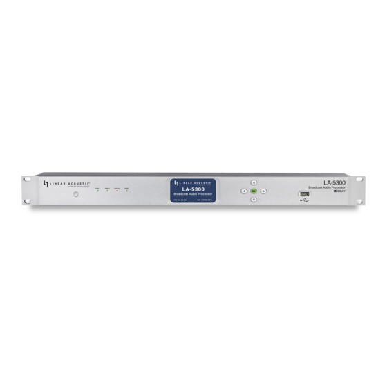
- Page 2 LA-5300 Front Panel Figure 1: Front panel The front panel of the LA-5300 includes the following: • Reset button for restarting the unit from the front panel (1A) • Four status LEDs indicating the status of each power supply (1B, 1C), the overall status of the unit (1D), and sync for the reference clock (1E) •...
- Page 3 LA-5300 Rear Panel Figure 2: Rear panel The rear panel includes the following connections: • Two RJ-45 Gigabit Ethernet connections, one for network remote control (2A) and one for AES67 I/O (2B) • Two independent 3Gb/s HD/SD-SDI inputs and outputs (2C) on female BNC connectors •...
-
Page 4: Installation And Initial Setup
Installation and Initial Setup Installation LA-5300 is a 1RU product intended to be permanently installed in standard 19 ½” equipment rack and secured with four standard rack screws. LA-5300 is fan cooled with air intakes and exhausts located on the side of the unit just behind the front panel, but whenever possible, it is recommended to leave 1RU of empty space above and below the unit. - Page 5 To set a fixed IP address for the Control port: • Press the Right button once to show the Information screen and once more to navigate to the IP Configuration (Control) screen • Press the Down button to highlight “Edit” •...
- Page 6 LA-5300. Once both LA-5300 and your computer are connected to your network, enter the IP address of the LA-5300 in the URL field of your browser. Once connected, the Home screen will appear.
- Page 7 Program/Passthrough switch (4C). Figure 4: I/O menu Routing audio into the LA-5300 is a two-step process. The first step is creating an input group from the available physical hardware inputs. The second step is routing the audio from these inputs to the program (processor) input.
- Page 8 (6A) and then clicking when the desired priority level (6B) is highlighted. The LA-5300 will look for audio first on inputs connected to Priority 1. If no signal is present, it will look to subsequent priorities in order.
- Page 9 Next, choose input signal type (PCM, DD+, or AC-4) from the Type dropdown menu (7A). Figure 7: Input signal type. To edit or delete a group, highlight then right click on the colored Edit rectangle (8A). Figure 8: Editing or deleting input group. Creating an Output Group The steps for creating an output group are identical to creating an input group, but with the Outputs menu.
-
Page 10: Clock Reference
Clock Reference Setting the Clock Reference Click on the Clock menu (9A). Use the dropdown menus to choose a Primary Reference Clock and a Secondary Reference Clock (9C) and, if needed, a VRef clock source (9E) The status of the selected Primary and Secondary Reference Clocks is shown to the right of the dropdown menu (9D). - Page 11 Signal Processing and Encoding Controls for Dolby® AC-4 encoding, upmixing, Nielsen and Verance watermark encoding, and monitoring are found in the Program 1 menu. Input metering (10A) and output metering (10B) for all channels and all I/O is also located on this page. Figure 10: Input and output meters.
- Page 12 AC-4 Encoding Click on the AC-4 Encoder dropdown menu (11A). Choose the appropriate Channel Mode (11B), Frame Rate (11C), Bit Rate (11G), Type (11F), Loudness Regulation standard (11E), and Language (11D) for your application. Figure 11: AC-4 encoding.
- Page 13 Upmixing Click on the Upmixing dropdown menu (12B). Choose the program input format using the Input Format dropdown menu (12C). By default, it is set to “Auto Detect” so that incoming content that already matches the desired output format will pass through unaltered, while 2- or 3-channel content will be automatically upmixed.
- Page 14 Nielsen Watermark Encoding Click on the Nielsen dropdown menu (13C). Click on the Enable dropdown menu (13B) to enable/disable Nielsen watermarking. Choose the appropriate process for your application in the Active Process dropdown menu (13A). Click on the SID, Check Digit, CSID, and/or CBET Check Digit fields (13D) to enter the specific codes as provided by Nielsen.
- Page 15 Verance Watermark Encoding Click on the Verance dropdown menu (14C). Click on the Enable dropdown menu (14B) to enable/disable Verance watermarking and the Calibrate dropdown menu (14A) to enable/disable the calibration mode. Click on the Server Code and Interval Code fields (14D) to enter the specific codes as provided by Verance.
- Page 16 Monitoring The LA-5300 includes a built-in AC-4 decoder for confidence monitoring. Click on the Monitor dropdown menu (15C) to access it. Click on the Channel Mode dropdown menu (15B) to choose a 5.1-channel output or a Lo/Ro or Lt/Rt downmix. The Target Reference Level dropdown menu (15A) sets the decoded monitor output level.
- Page 17 User Warnings and Cautions The installation and service instructions in this manual are for use by qualified personnel only. To avoid electric shock, do not perform any servicing other than that contained in the operating instructions unless you are qualified to do so. Refer all servicing to qualified personnel This instrument has an auto-ranging line voltage input.
- Page 18 Do not place the units on a carpet, bedding, or other materials that could interfere with any panel ventilation openings. If the equipment is used in a manner not specified by the manufacturer, the protection provided by the equipment may be impaired. USA CLASS A COMPUTING DEVICE INFORMATION TO USER WARNING This equipment generates, uses, and can radiate radio-frequency energy.
- Page 19 The Telos Alliance makes no endorsement of any particular product for any purpose, nor claims any responsibility for operation or accuracy. We reserve the right to make improvements or changes in the products described in this manual which may affect the product specifications, or to revise the manual without notice. This document and its content are copyrighted by TLS Corporation and may not be copied, reproduced, or distributed in any form without expressed written permission.
- Page 20 We will issue a return authorization number, which must be written on the exterior of your shipping container. Please do not include cables or accessories unless specifically requested by the Technical Support Engineer. Be sure to adequately insure your shipment for its replacement value.
Need help?
Do you have a question about the LA-5300 and is the answer not in the manual?
Questions and answers