Table of Contents
Advertisement
Quick Links
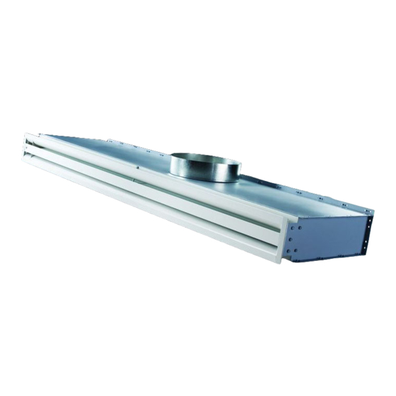
THERMA-FUSER™
EL - DDC INTEROPERABLE LINEAR VAV DIFFUSER
INSTALLATION, BALANCING & MAINTENANCE
Table Of Contents
INSTALLATION INSTRUCTIONS...........................................................................................2
CONNECTING WIRING ..........................................................................................................2
NETWORK CREATION AND COMMISSIONING OF EL DIFFUSERS ..................................2
EL...........................................................................................................................................4
................................................................................................................................................7
V
AIR DENSITY COMPENSATION............................................................................................7
SYSTEM AIR BALANCING ....................................................................................................7
TROUBLE SHOOTING ...........................................................................................................8
MAINTENANCE ....................................................................................................................11
CONTROLLING THE SYSTEM.............................................................................................11
MEASURING ENERGY CONSUMPTION.............................................................................15
TWO YEAR WARRANTY .....................................................................................................15
DAMAGED FREIGHT CLAIM PROCEDURE
When the diffusers are received, inspect for damage, which may have occurred during shipment. If damage is
evident, it should be noted on the carrier's freight bill. A written request for inspection by the carrier's agent should
be made at once.
STORAGE
Cartons should always be stacked on end. Do not stack cartons flat on the sides. Excessive weight may cause
damage to the diffusers.
Do not store for prolonged times at temperatures exceeding 130°F(56°C). Acceptable humidity level 5-95% relative
humidity noncondensing.
IDENTIFICATION
Models are factory shipped one per carton. The model designation is on the diffuser and on the carton.
INSTALLATION PRECAUTIONS
When installing diffusers make sure construction debris does not enter the diffuser or duct system.
Because the EL controls room temperature by sensing the room air induced up from the room, care should be
taken not to disturb room air induction and entrainment
.......................................................................................................................3
..........................................................................................................3
..........................................................................................................................7
...............................................................................................................7
...................................................................................................3
FORM 54.2 REV 0703
Advertisement
Table of Contents

Summary of Contents for acutherm THERMA-FUSER EL
-
Page 1: Table Of Contents
FORM 54.2 REV 0703 THERMA-FUSER™ EL - DDC INTEROPERABLE LINEAR VAV DIFFUSER INSTALLATION, BALANCING & MAINTENANCE Table Of Contents INSTALLATION INSTRUCTIONS...................2 CONNECTING WIRING ......................2 NETWORK CREATION AND COMMISSIONING OF EL DIFFUSERS ........2 ........................3 REATE A AKER ETWORK EL T ....................3 NTRODUCE AKER ETWORK... -
Page 2: Installation Instructions
Connect 24 VAC to the ’24 VAC’ terminal of the EL. NETWORK CREATION AND COMMISSIONING OF EL DIFFUSERS Download the XIF file from Acutherm web site: www.acutherm.com. This part of the document is prepared only for users having LonMaker For Windows as the network management tool. -
Page 3: Create A Lonmaker Network
Create a LonMaker Network 1. To create a new network: From Windows desktop click on Start -> Programs -> LonMaker For Windows. From the first window screen of LonMaker click on the ‘New Network’ button then enter the new network name in the ‘Network Name’... -
Page 4: Configure The El
Configure The EL The EL unit is shipped with the default values shown below. When configuring, review the default values and change only what is necessary Configuration Variables Symbol On Screen Function Description Default value Range Available (SCPTs, SNVTs) 23°C (73.4°F), The temperature setpoint of 25°C (77°F), the space to be maintained... - Page 5 Do not change from Minimum Reserved for future use. SCPTminFlow Flow factory default setting. Minimum Do not change from Reserved for future use. Flow SCPTminFlowStby factory default setting. Standby Do not change from Duct Area Reserved for future use. SCPTductArea factory default setting.
- Page 6 Forces the EL into a lower energy consumption mode. For example, an opened 0.0 0 ( 2 fields Energy window could close the nviEnergyHoldOff separated by a 0 to 100%, 0 or 1 Hold-Off diffuser in the cooling mode or space) cause the EL to go to the unoccupied setpoint if in the...
-
Page 7: Power Failure
Fan_output : Not used In_alarm : Refer to Acutherm EL Trouble Shooting Guide Power Failure Configuration values are stored in non-volatile memory so that the EL diffusers can resume normal operation when power is restored after failure. Input network variable values will be restored only if updated via network. -
Page 8: Trouble Shooting
Note: Diffuser noise is caused by higher velocity air through the diffuser which is caused by a high static pressure. Acutherm recommends a static pressure no higher than .25” wg/ 62 Pa but some system designers may accept higher noise levels and opt for a higher static pressure. Care should be taken not to exceed the design maximum static pressure at the takeoff to the first EF diffuser after the static pressure control or, if none, after the fan. - Page 9 Remove the controller cover and measure the voltage across the terminals marked heat. See sketch of controller. If the voltage is not according to the above table, complete step 3 “EL Electrical” before contacting Acutherm.
- Page 10 If the resistance is outside the range, check the common terminal connections. If all common wires are in contact with the terminals and the resistance is still outside the range, contact Acutherm.
-
Page 11: Maintenance
An error message means resetting was unsuccessful. If so, try resetting by power off and then on. Wait 2 to 3 minutes after resetting before rechecking the condition of the EL unit. If it still has a communication problem or signals an out-of-range reference voltage, contact Acutherm. MAINTENANCE The moving parts of the EL diffuser have no maintenance or lubrication requirements. - Page 12 Flow Chart For AHU Controller (Main Page) START FROM WARM UP IS OPTIONAL OTHER RESET/ COOL OFF OTHERWISE GO TO FLOW POWERED UP HEAT OFF OCCUPIED CHARTS FAN OFF WARM UP HAS IT BEEN OCCUPIED TURN THE FAN TIME FOR FLAG 10 SECS? MODE ?
- Page 13 Flow Chart For AHU Controller (Occupied Mode) REVIEW ROOM SET PTS WE RECOMMEND A 30 EVERY 30 SECS WHEN IN MIN. TIME DELAY RECIRCULATION BETWEEN MODES START (COOLING & HEATING) MORE THAN HAS 30 SEC PUT SYSTEM IN IS SYSTEM IN IS 30 MIN.
- Page 14 Flow Chart For AHU Controller (Warm Up) START OF MORNING REVIEW ROOM SET PTS WARM UP EVERY 30 SECS MORE THAN IS MONITOR 30 SEC TIMER HALF ROOM SYSTEM MODE = FLAG SET? EXPIRED? TEMPS < HEAT SETPTS? HEAT OFF MORE THAN SET MONITOR 30 MIN TIMER...
-
Page 15: Measuring Energy Consumption
Acutherm and found defective and provided the diffusers have been given normal and proper usage and all parts and controls remain unaltered. Acutherm makes NO WARRANTY OF MERCHANTABLILITY OF PRODUCTS OR OF THEIR FITNESS FOR ANY PURPOSE OR ANY OTHER EXPRESS OR IMPLIED WARRANTY WHICH EXTENDS BEYOND THE LIMITED WARRANTY ABOVE.
Need help?
Do you have a question about the THERMA-FUSER EL and is the answer not in the manual?
Questions and answers