Table of Contents
Advertisement
Quick Links
Advertisement
Table of Contents

Related Manuals for Monoprice 18801


Summary of Contents for Monoprice 18801
- Page 1 WolfPack 2 - Channel 120W Mixer Amp with Microphone Input 18801 User’s Manual...
-
Page 2: Table Of Contents
CONTENTS SAFETY WARNINGS AND GUIDELINES ..................................3 INTRODUCTION ..............................................4 FEATURES ................................................5 CUSTOMER SERVICE ............................................. 5 PACKAGE CONTENTS ........................................... 5 PRODUCT OVERVIEW ..........................................6 Front Panel ..............................................6 Rear Panel ............................................... 7 INPUT CONNECTIONS ..........................................7 Single Mono Balanced Microphone or Line Level Input ........................7 Single Mono Unbalanced Line Level Input ................................ -
Page 3: Safety Warnings And Guidelines
SAFETY WARNINGS AND GUIDELINES Please read this entire manual before using this device, paying extra attention to these safety warnings and guidelines. Please keep this manual in a safe place for future reference. This device is intended for indoor use only. ... -
Page 4: Introduction
Take care to prevent damage to the power cord. Do not allow it to become crimped, pinched, walked on, or become tangled with other cords. Ensure that the power cord does not present a tripping hazard. Never unplug the unit by pulling on the power cord. Always grasp the connector head. -
Page 5: Features
FEATURES Can be configured for 60-watts/channel stereo, dual 60-watt mono, or bridged 120-watt mono modes Two balanced mono inputs using Euroblock connectors Two unbalanced line level stereo RCA inputs Mic/Line switch for the balanced inputs Separate volume controls for each input ... -
Page 6: Product Overview
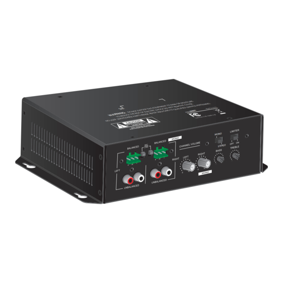
PRODUCT OVERVIEW Front Panel 1. Left Channel Balanced Euroblock Input 2. Left Channel Unbalanced Stereo RCA Input 3. Mic/Line Selector Switches for the Balanced Inputs 4. Right Channel Unbalanced Stereo RCA Input 5. Right Channel Balanced Euroblock Input 6. Left Channel Volume Control 7. -
Page 7: Rear Panel
Rear Panel 12. AC Power Input Connector 13. Power Switch 14. Power LED Indicator 15. Speaker Output Euroblock Connector INPUT CONNECTIONS Single Mono Balanced Microphone or Line Level Input Perform the following steps to connect a single, balanced microphone or line level input: 1. -
Page 8: Single Mono Unbalanced Line Level Input
7. Set the MONO/DUAL switch to the MONO position. Two Speakers 8. Continue with the instruction steps in either the section or the Single Bridged Speaker section. Single Mono Unbalanced Line Level Input Perform the following steps to connect a single, unbalanced line level source in mono mode. -
Page 9: Dual Mono Unbalanced Line Level Inputs
7. Repeat steps 3-6 on the LEFT channel balanced input for your second balanced input. 8. Set the MONO/DUAL switch to the DUAL position. Two Speakers 9. Continue with the instruction steps in the section. Dual Mono Unbalanced Line Level Inputs Perform the following steps to connect two line stereo level sources in dual mono mode. -
Page 10: Output Connections
OUTPUT CONNECTIONS Two Speakers The amplifier can be connected to two speakers for either dual mono or stereo operation. In this configuration each speaker is driven by a dedicated 60-watt amplifier. In this configuration the amp can drive 4-8 ohm speaker loads. For dual mono operation, the speakers should be located in different zones, while for stereo operation, the speakers should be located in the same zone. -
Page 11: Operation
3. Insert the negative lead from the speaker into the LEFT + connector, then tighten the screw. 4. Insert the positive lead from the speaker into the RIGHT + connector, then tighten the screw. OPERATION General Set the LIMITER switch to the ON position to reduce the output signal to prevent clipping. -
Page 12: Technical Support
HDTVSupply during regular business hours, 7 days a week. You can also get assistance through email by sending a message to support@hdtvsupplycom SPECIFICATIONS Model 18801 Power Output 1x 60 watts, 2x 60 watts, or 1x 120 watts Frequency Response 50 Hz ~ 18 kHz Total Harmonic Distortion less than 0.5% @ 1kHz at 1/3 full power... -
Page 13: Regulatory Compliance
REGULATORY COMPLIANCE Notice for FCC This device complies with Part 15 of the FCC rules. Operation is subject to the following two conditions: (1) this device may not cause harmful interference, and (2) this device must accept any interference received, including interference that may cause undesired operation. Modifying the equipment without upply’s authorization may result in the equipment no longer complying with FCC requirements for Class B digital devices.
Need help?
Do you have a question about the 18801 and is the answer not in the manual?
Questions and answers