peplink Pepwave Device Connector Rugged User Manual
For more information, please visit peplink.com

Related Manuals for peplink Pepwave Device Connector Rugged


Summary of Contents for peplink Pepwave Device Connector Rugged
- Page 1 Pepwave Device Connector User Manual Pepwave Product: Device Connector Rugged Pepwave Firmware 1.1 June 2020 ...
-
Page 2: Table Of Contents
Table of Contents 1. Getting Started 1.1 What’s in the Box 1.2 Get to Know Your Device Connector 1.3 Access the Web Admin Interface 1.3.1 Connect by Ethernet 1.3.2 Connect by Wi-Fi 1.4 Choose Your Connection Mode 2 Configuring the LAN interface(s) 2.1 Network Settings 2.2 Port Setting 3 Configuring the WAN Interface(s) - Page 3 5.12 Reboot 6 Tools 6.1 Ping 6.2 Traceroute 6.3 Wake-on-LAN 7 PEPVPN 8 Port Forwarding 9 NAT Mappings 10 QoS 10.1 Bandwidth Control 10.2 Application 10.2.1 Application Prioritization 10.2.2 Prioritization for Custom Applications 10.2.3 DSL/Cable Optimization 11 Miscellaneous Settings 11.1 Certificate Manager 12 Status 12.1 Device 12.2 Client List...
-
Page 4: Getting Started
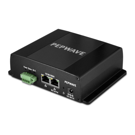
1. Getting Started 1.1 What’s in the Box DCS-RUG ● 12V power supply ● 3x dual-band 5dBi omni antenna G et to Know Your Device Connector 1.2 Device Connector Rugged... -
Page 5: Access The Web Admin Interface
A ccess the Web Admin Interface 1.3 There are two ways to access the W eb Admin page. 1.3.1 Connect by Ethernet To access the Web Admin page by Ethernet, your PC must be in the same subnet as the Device Connector ... -
Page 6: Connect By Wi-Fi
1.3.2 Connect by Wi-Fi Connect to the SSID: PEPWAVE_XXX where XXXX represents the last four digits of your device’s serial number (e.g. 7D6E). Passphrase is the last 8 hexadecimal digits of your device’s LAN MAC address (e.g. DDC3CCC0) Now you are ready to start the first time configuration of the Pepwave Device Connector. -
Page 7: Configuring The Lan Interface(S)
2 Configuring the LAN interface(s) 2.1 Network Settings LAN i nterface settings are located at N etwork>LAN>Network Settings/Port Settings. B egin setting up your physical LAN by entering IP settings (VLAN configuration will be covered following physical LAN setup). This represents the LAN interfaces that are active on your router (including VLAN). - Page 8 DHCP Server Settings DHCP Server When this setting is enabled, the DHCP server automatically assigns an IP address to each computer that is connected via LAN and configured to obtain an IP address via DHCP. The Pepwave router’s DHCP server can prevent IP address collision on the LAN. IP Range &...
-
Page 9: Port Setting
address per line in the provided text area input control. Each option can be defined once only. DHCP This setting reserves the assignment of fixed IP addresses for a list of computers on the LAN. The computers to be assigned fixed IP addresses on the LAN are identified by Reservation their MAC addresses. -
Page 10: Configuring The Wan Interface(S)
LAN Physical Settings Speed This is the port speed of the LAN interface. It should be set to the same speed as the connected device to avoid port negotiation problems. When a static speed is set, you may choose whether to advertise its speed to the peer device. A uto is selected by default. -
Page 11: Wi-Fi Wan Settings (Wi-Fi Mode Only)
You can also set priorities on the Dashboard. Click the Details button in the corresponding row to modify the connection setting. Important Note Connection details will be changed and become effective immediately after clicking the S ave and Apply b utton. 3.1 Wi-Fi WAN Settings (Wi-Fi Mode Only) To access Wi-Fi WAN settings, click ... - Page 12 Wi-Fi Connection Settings WAN Connection Enter a name to represent this WAN connection. Name Standby State This setting specifies the state of the WAN connection while in standby. The available options are Remain Connected (hot standby) and Disconnect (cold standby). This setting specifies the maximum transmission unit.
- Page 13 Channel Determine whether the channel will be automatically selected. If you select custom, the following table will appear: Selection Data Rate This option allows you to select a specific bit rate for data transfer over the device’s Wi-Fi network. By default, Auto is selected. Output Power This option is for specifying the transmission output power for the Wi-Fi AP.
- Page 14 Health Check Settings Method This setting specifies the health check method for the WAN connection. This value can be configured as Disabled, PING, DNS Lookup, or HTTP. The default method is DNS Lookup. For mobile Internet connections, the value of Method can be configured as Disabled or SmartCheck.
- Page 15 DNS lookups will be issued to test connectivity with target DNS servers. The connection will be treated as up if DNS responses are received from one or both of the servers, regardless of whether the result was positive or negative. Health Check This field allows you to specify two DNS hosts’...
-
Page 16: Creating Wi-Fi Connection Profiles
This setting specifies the number of consecutive successful ping/DNS lookup responses that must be received before the Peplink Balance treats a previously down WAN connection as up again. By default, Recover Retries is set to 3. Using the default setting, a WAN connection that is treated as down will be considered as up again upon receiving three consecutive successful ping/DNS lookup responses. - Page 17 Wi-Fi Connection Profile Settings Type Select whether the network will connect automatically or manually. Network Name Enter a name to represent this Wi-Fi connection. (SSID) Security This option allows you to select which security policy is used for this wireless network. Available options: ●...
-
Page 18: Wan Health Check
3.2 WAN Health Check To ensure traffic is routed to healthy WAN connections only, the Pepwave router can periodically check the health of each WAN connection. The health check settings for each WAN connection can be independently configured via N etwork>WAN>Details . Health Check Settings Method This setting specifies the health check method for the WAN connection. - Page 19 Health Check Method: DNS Lookup DNS lookups will be issued to test connectivity with target DNS servers. The connection will be treated as up if DNS responses are received from one or both of the servers, regardless of whether the result was positive or negative.
- Page 20 Other Health Check Settings Timeout This setting specifies the timeout in seconds for ping/DNS lookup requests. The default timeout is 5 seconds . Health Check This setting specifies the time interval in seconds between ping or DNS lookup requests. The default health check interval is ...
-
Page 21: Wireless Ssid
4.1 Wireless SSID Wireless network settings, including the name of the network (SSID) and security policy, can be defined and managed in this section. Click A DD to create a new network profile, or click the existing network profile to modify its settings. -
Page 22: Settings
IGMP Snooping To allow the Pepwave router to listen to internet group management protocol (IGMP) network traffic, select this option. Layer 2 Isolation Layer 2 refers to the second layer in the ISO Open System Interconnect model. When this option is enabled, clients on the same VLAN, SSID, or subnet are isolated to that VLAN, SSID, or subnet, which can enhance security. - Page 23 Wi-Fi Radio Settings Operating This option sets the country whose regulations the Pepwave router follows. Country Wi-Fi Antenna Choose from the router's internal or optional external antennas, if so equipped. Important Note...
- Page 24 Per FCC regulations, the country selection is not available on all models marketed in the US. All US models are fixed to US channels only. Wi-Fi AP Settings Protocol This option allows you to specify which client association requests will be accepted.
-
Page 25: System Settings
Distance/Time Select the distance you want your Wi-Fi to cover in order to adjust the below parameters. Default values are recommended. Converter Slot Time This field is for specifying the wait time before the Device Connector transmits a packet. By default, this field is set to 9 µs . ACK Timeout... - Page 26 Admin Account UI User Account UI A web login session will be logged out automatically when it has been idle longer than the W eb Session Timeout . Before the session expires, you may click the Logout button in the web admin to exit the session. 0 hours 0 minutes...
- Page 27 Admin Settings This field allows you to define a name for this Pepwave router. By default, R outer Router Name Name is set as D CS_XXXX , where X XXX refers to the last 4 digits of the unit’s serial number.
- Page 28 Read-only User Name is set as u ser by default, but can be changed, if desired. Read-only User Name User Password This field allows you to specify a new user password. Once the user password is set, the read-only user feature will be enabled. Confirm User This field allows you to verify and confirm the new user password.
-
Page 29: Operating Mode
● H TTPS ● H TTP/HTTPS Web Admin This field is for specifying the port number on which the web admin interface can be accessed. Port Web Admin This option is for specifying the network interfaces through which the web admin interface can be accessed: Access ●... -
Page 30: Time
Do not disconnect the power during firmware upgrade process. Do not attempt to upload a non-firmware file or a firmware file that is not supported by Peplink. Upgrading the Pepwave router with an invalid firmware file will damage the unit and may void the warranty. -
Page 31: Schedule
Time Settings Time Zone This specifies the time zone (along with the corresponding Daylight Savings Time scheme). The T ime Zone value affects the time stamps in the Pepwave router’s event log and e-mail notifications. Check S how all to show all time zone options. Time Server This setting specifies the NTP network time server to be utilized by the Pepwave router. -
Page 32: Email Notification
Edit Schedule Profile Enabling Click this checkbox to enable this schedule profile. Note that if this is disabled, then any associated features will also have their scheduling disabled. Name Enter your desired name for this particular schedule profile. Schedule Click the drop-down menu to choose pre-defined schedules as your starting point. Please note that upon selection, previous changes on the schedule map will be deleted. - Page 33 Check the box to enable SMTPS. When the box is checked, S MTP Port w ill be SSL Encryption changed to 465 automatically. This field is for specifying the SMTP port number. By default, this is set to 2 5 ; when SMTP Port SSL Encryption ...
-
Page 34: Event Log
The Pepwave router can also send push notifications to mobile devices that have our Mobile Router Utility installed. Check the box to activate this feature. For more information on the Router Utility, go to: www.peplink.com/products/router-utility 5.8 SNMP SNMP or simple network management protocol is an open standard that can be used to collect information about the Pepwave router. -
Page 35: Incontrol
This option allows you to enable SNMP version 3. 5.9 InControl InControl is a cloud-based service which allows you to manage all of your Peplink and Pepwave devices with one unified system. With it, you can generate reports, gather statistics, and configure your devices automatically. All of this is now possible... -
Page 36: Configuration
When this check box is checked, the device's status information will be sent to the Peplink InControl system. This device's usage data and configuration will be sent to the system if you enable the features in the system. Alternately, you could also privately host InControl. Simply check the box beside the “Privately Host InControl”... -
Page 37: Feature Add-Ons
5.11 Feature Add-ons Pepwave devices have features that can be activated upon purchase. Once the purchase is complete, you will receive an activation key. Enter the key in the A ctivation Key field, click A ctivate , and then click A pply Changes 5.12 Reboot This page provides a reboot button for restarting the system. -
Page 38: Traceroute
6.2 Traceroute The traceroute test tool traces the routing path to the destination through a TM particular Ethernet interface or a SpeedFusion connection. The traceroute test utility is located at S ystem>Tools>Traceroute . Peplink routers can send magical Packets... -
Page 39: Wake-On-Lan
A system administrator can use the traceroute utility to analyze the connection path of a LAN/WAN connection. 6.3 Wake-on-LAN Peplink routers can send special “magic packets” to any client specified from the Web UI. To access this feature, navigate to S ystem>Tools>Wake-on-LAN. -
Page 40: Pepvpn
7 PEPVPN To configure PepVPN and SpeedFusion, navigate to A dvanced>PepVPN The local LAN subnet and subnets behind the LAN (defined under S tatic Route on the LAN settings page) will be advertised to the VPN. All VPN members (branch offices and headquarters) will be able to route to local subnets. - Page 41 N ew Profile button). Each profile specifies the settings for making VPN connection with one remote Pepwave or Peplink device. Click the S ave button to create and save a new VPN connection profile for making a VPN connection.
-
Page 42: Port Forwarding
IP addresses until it succeeds in making a connection. If the field is empty, the Peplink Balance will wait for connection from the remote peer. Therefore, at least one of the two VPN peers must specify this value. - Page 43 Port Forwarding Settings This setting specifies whether the inbound service takes effect. When E nable is checked, Enable the inbound service takes effect: traffic is matched and actions are taken by the Pepwave router based on the other parameters of the rule. When this setting is disabled, the inbound service does not take effect: the Pepwave router disregards the other parameters of the rule.
-
Page 44: Nat Mappings
setting. For example, with I P Protocol set to T CP , and P ort set to S ingle Port and Service Port 80, TCP traffic received on port 80 is forwarded to the configured servers via port 80. - Page 45 NAT Mapping Settings LAN Client(s) NAT mapping rules can be defined for a single LAN IP Address, an IP Range, or an IP Network. Address This refers to the LAN host’s private IP address. The system maps this address to a number of public IP addresses (specified below) in order to facilitate inbound and outbound traffic.
-
Page 46: Qos
10 QoS 10.1 Bandwidth Control You can define a maximum download speed (over all WAN connections) and upload speed (for each WAN connection) that each individual Staff and Guest member can consume. No limit can be imposed on individual Manager members. By default, download and upload bandwidth limits are set to unlimited (set as ... -
Page 47: Dsl/Cable Optimization
10.2.3 DSL/Cable Optimization DSL/cable-based WAN connections have lower upload bandwidth and higher download bandwidth. When a DSL/cable circuit's uplink is congested, the download bandwidth will be affected. Users will not be able to download data at full speed until the uplink becomes less congested. D SL/Cable Optimization can relieve such an issue. - Page 48 System Information Router Name This is the name specified in the R outer Name field located at S ystem>Admin Security . Model This shows the model name and number of this device. Product Code If your model uses a product code, it will appear here. Hardware This shows the hardware version of this device.
-
Page 49: Client List
Diagnostic The D ownload link is for exporting a diagnostic report file required for system investigation. Report Remote Click T urn on to enable remote assistance. Assistance The second table shows the MAC address of each LAN/WAN interface connected. To view your device’s End User License Agreement (EULA), click Important Note If you encounter issues and would like to contact the Pepwave Support Team (... -
Page 50: Event Log
Current PepVPN status information is located at S tatus>PepVPN. C lick on the corresponding peer name to explore the WAN connection(s) status and subnet information of each VPN peer.Click the button for a chart displaying real-time throughput, latency, and drop-rate information for each WAN connection 12.4 Event Log Event log information is located at ... -
Page 51: Bandwidth
12.5 Bandwidth This section shows bandwidth usage statistics and is located at S tatus>Bandwidth . Bandwidth usage at the LAN while the device is switched off (e.g., LAN bypass) is neither recorded nor shown. 12.5.1 Real Time The D ata transferred since installation t able indicates how much network traffic has been processed by the device since the first bootup. -
Page 52: Daily
12.5.3 Daily This page shows the daily bandwidth usage for all WAN connections, with the option of viewing each individual connection. Select the connection to check from the drop-down menu. If you have enabled the Bandwidth Monitoring f eature , the C urrent Billing Cycle t able for that WAN connection will be displayed. -
Page 54: Monthly
12.5.4 Monthly All WAN Monthly Bandwidth Usage... -
Page 55: Restoration Of Factory Defaults
Restoration of Factory Defaults To restore the factory default settings on a Pepwave Device Connector Rugged, follow the steps below: Locate the reset button on the front or back panel of the Pepwave Device Connector Rugged router. With a paperclip, press and keep the reset button pressed. -
Page 56: Appendix
Appendix Federal Communication Commission Interference Statement This equipment has been tested and found to comply with the limits for a Class B digital device, pursuant to Part 15 of the FCC Rules. These limits are designed to provide reasonable protection against harmful interference in a residential installation. - Page 57 Peplink. Disclaimer Peplink does not assume any liability arising out of the application or use of any products, or software described herein. Neither does it convey any license under its patent right nor the patent rights of others. Peplink further reserves the right to make changes in any products described herein without notice.
Need help?
Do you have a question about the Pepwave Device Connector Rugged and is the answer not in the manual?
Questions and answers