Advertisement
Quick Links
CONTROLLED DOCUMENT
Work Instruction No.
Author Matt Beckerdite
Description Assembly of Model SSPC closed impeller pump
Safety Equipment
Safety Guidelines
Equipment and Tools See Step 1 that describes the tools used
Introduction: This procedure describes the process for assembling a Model SSPC enclosed impeller pump. These pumps have a catalog number that
begin with a C1 and C2. The BOM will list the specific parts used such as o-rings, mechanical seals, cases, motor etc.
WORK INSTRUCTION
Flexible Gloves to protect against cuts
WI_AB_CXXXXXXXXX
Rel. Date
11/26/13
Rev.
a
Advertisement

Related Manuals for ASP SSPC


Summary of Contents for ASP SSPC
- Page 1 Equipment and Tools See Step 1 that describes the tools used Introduction: This procedure describes the process for assembling a Model SSPC enclosed impeller pump. These pumps have a catalog number that begin with a C1 and C2. The BOM will list the specific parts used such as o-rings, mechanical seals, cases, motor etc.
- Page 2 WORK INSTRUCTION WI_AB_CXXXXXXXXX Work Instruction No. Exploded View Diagram of SSPC Pump Assembly...
- Page 3 See work instruction WI_M_DTMOT for details on this procedure. Nidec motors will use a ¼-20” LH rotation screw and come tapped from the factory, while all others use a ¼”- 28 RH rotation locking screw. This hole is drilled and tapped at ASP. Step 3 Gather Parts Gather the parts located on the work order/BOM.
- Page 4 WORK INSTRUCTION WI_AB_CXXXXXXXXX Work Instruction No. Step 4 Remove back plug from motor The motor manufacturer supplies a plug in the back of the motor. It can be seen in this picture as a black plug at the center of the motor. This plug must be removed in order to access the shaft during impeller installation.
- Page 5 WORK INSTRUCTION WI_AB_CXXXXXXXXX Work Instruction No. Step 6 Inspecting the Installed Seal for Proper Installation View the seal from the backside to ensure the seal has been pressed all the way into the sealplate bore. There should be no gap present between the seal and the bore. Step 7 Setup Motor for Component Installation and Remove Slinger Setup the motor on its rear end.
- Page 6 WORK INSTRUCTION WI_AB_CXXXXXXXXX Work Instruction No. Step 9 Re-install Slinger Place the slinger back over the shaft and press it against the adapter plate Step 10 Install Adapter Plate Screws Install the 4 motor mounting bolts by hand. This prevents the threads from galling or breaking with installation using an air ratchet.
- Page 7 WORK INSTRUCTION WI_AB_CXXXXXXXXX Work Instruction No. Step 12 Installing the O-Ring and Rotating Half of the Mechanical Seal Install the o-ring onto the sealplate as shown in the picture. The o-ring should not be twisted or rolled. Place one side of the o-ring over the sealplate. With two fingers, stretch the o-ring over the other side while being careful not to roll the o-ring.
- Page 8 WORK INSTRUCTION WI_AB_CXXXXXXXXX Work Instruction No. Step 14 Installing the Impeller Screw the impeller onto the motor shaft in a clockwise direction. In order to completely tighten the impeller, place a screwdriver into slot located in the back of the motor and spin the impeller.
- Page 9 WORK INSTRUCTION WI_AB_CXXXXXXXXX Work Instruction No. Step 16 (For 3 Phase motor Only) Installing the Locking Screw and Washer Skip this step if the motor is single phase!!! Place the screw listed on the work order BOM into the motor shaft. -Left Hand screws will be rotated counter clockwise to tighten (Nidec Motors) -Right Handed screws will be tightened clockwise to tighten Rotate the screw by hand until it stops at the impeller hub.
- Page 10 WORK INSTRUCTION WI_AB_CXXXXXXXXX Work Instruction No. Step 19 Installing the Case Assembly Place the case onto the sealplate, over the o-ring. Ensure the holes in the case flange, sealplate, and motor adapter are aligned by placing an extended 3/16” allen bit through the holes. Wiggle the bit to line up all the holes.
- Page 11 WORK INSTRUCTION WI_AB_CXXXXXXXXX Work Instruction No. Step 20 Inspecting the Assembly for Proper Baseplate If the motor is a footed motor, or an assembly with no base (catalog number ends with L), skip this step. Set the motor on its foot/base. Check the base to ensure the radius of the baseplate matches the motor diameter.
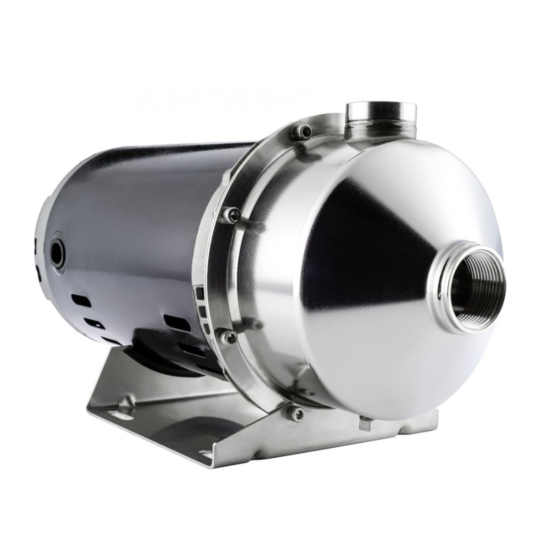
- Page 12 WORK INSTRUCTION WI_AB_CXXXXXXXXX Work Instruction No. Step 23 Completed Assembly A completed pump assembly with a stainless steel baseplate can be seen in the picture on the left Date Revision Change 11/26/13 Initial Release by Matt Beckerdite...
Need help?
Do you have a question about the SSPC and is the answer not in the manual?
Questions and answers