Table of Contents
Advertisement
Quick Links
Product Name:
Product Description:
Product Number:
------------------------------------------------------------------------------------------------------------------------
IMPORTANT NOTES:
Please thoroughly read and understand these instructions before commencing this installation.
RECOMMENDATIONS
•
Turbosmart recommends that your BOV controller is fitted and adjusted by an appropriately qualified technician
Turbosmart recommends that a boost gauge be permanently fitted to the vehicle
------------------------------------------------------------------------------------------------------------------------
Please check that the following items have been provided in your BOV Controller Kit
Quantity
1
BOV Controller Unit
1
Race Port assembly
2m
2 core wire
1
Heat shrink
2
Double sided adhesive
2
M3 X 30 Screws
2
M3 Nuts
1
3 Port solenoid
3
1/8 NPT nipples
1.2m
6.3mm Reinforced pressure tube
1
Solenoid Bracket
2
M3X20 SHCS
2
5 amp Fuses
1
M6 Nut
1
M6 X 25 SHCS
1
M6 Washer
10
Cable ties
1
Crimp ring terminal
4
Hose clamps
1
8 way wiring loom
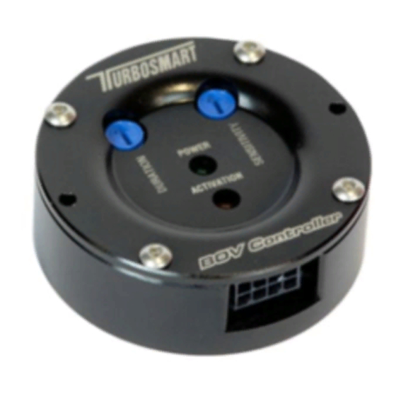
FUNCTIONALITY
The BOV controller works by detecting a negative voltage change in throttle position. It then energises the solenoid to vent all of the air
out of the BOV cap, causing a pressure differential between the piston of the BOV and the cap which will vent pressure from the intake
system. There are 2 parameters that can be adjusted to tune the controller for optimum performance; duration and sensitivity. The green
LED shows that the BOV controller is on. The yellow LED shows when the solenoid is activated.
LAYOUT
INSTALLATION
Mount the unit away from any heat source and moisture. Wire up the unit as per diagram. Do not connect the unit to a power supply
which will have a greater voltage than 14V DC. Unused wires must be insulated with electrical tape so that they do not touch
other wires or the chassis
1. ORANGE = +5V (For external TPS) – OPTIONAL if your engine does not have a OEM TPS
2. GREEN = 0V (For external TPS) - OPTIONAL if your engine does not have a OEM TPS
3. WHITE = TPS signal Input
4. YELLOW = Solenoid trigger signal
5. GREY = Disable Trigger wire (Ground to disable Controller) - OPTIONAL
6. BROWN = Enable Trigger wire (Ground to keep solenoid energised) - OPTIONAL
7. BLACK = Controller Ground
8. RED = +12V (USE SUPPLIED 5A Fuse inline)
BOV Controller Kit
Electronic BOV controller
TS-0304-100X
Description
Duration adjustment
Activation LED
BOV Controller
Blow off valve fitted with orange inner spring and stainless steel weld flange
Connect BOV Controller to solenoid
Insulating soldered joints
Surface mounting BOV controller
Mounting BOV controller
Mounting BOV controller
Controls pressure to BOV
Connects solenoid to hose
To connect the solenoid to the BOV
Mounting the solenoid
Mounting bracket to solenoid
To protect the BOV controller and solenoid from voltage problems
Secure solenoid bracket to car
Secure solenoid bracket to car
Secure solenoid bracket to car
Securing vacuum tube and wires
For ground connection
Securing all pressure lines
Connects BOV Controller to devices and power
Sensitivity adjustment
Power LED
Mounting Holes
1
Use
1
2
3
4
5
6
7
8
Looking into BOV
Controller
Advertisement
Table of Contents

Related Manuals for Turbosmart BOV Controller Kit


Summary of Contents for Turbosmart BOV Controller Kit
- Page 1 Please thoroughly read and understand these instructions before commencing this installation. RECOMMENDATIONS • Turbosmart recommends that your BOV controller is fitted and adjusted by an appropriately qualified technician Turbosmart recommends that a boost gauge be permanently fitted to the vehicle...
- Page 2 SOLENOID CONNECTION Wire from solenoid: Connect to Ignition activated 12V Power source via fuse Supplied 5A fuse Yellow wire from control unit (1) Vent to atmosphere Wire from solenoid (2) To pressure (3) To pressure source Electrical connection nipple on BOV Connect one wire of the solenoid to a fused (use supplied fuse) ignition activated 12V power source and connect the other wire to the Solenoid trigger signal (Yellow) on the BOV controller unit.
- Page 3 Put the V-Band clamp over the adapter before re-installing the O-Ring seal and the Race Port Open the V-Band clamp and place in position. Tighten the V-Band clamp screw until it is finger tight then turn an additional 2.5 turns or 4 Nm (3 ft/lbs) with an allen key.
- Page 4 Slowly push the top cap down on the lower diaphragm housing in a vice or press. As the cap reaches the diaphragm, line up the notches in the cap (Figure 1) with the cut outs (Figure 2) in the lower diaphragm housing. Carefully push the cap down till the cap is home on the lower diaphragm housing.
- Page 5 If found to be defective, it will be replaced or repaired if returned prepaid along with proof of date of purchase. This shall constitute the sole remedy of the purchaser and the sole liability of Turbosmart to the extent permitted by law, the foregoing is exclusive and in lieu of all other warranties or representations whether expressed or implied, including any implied warranty of merchantability or fitness.
Need help?
Do you have a question about the BOV Controller Kit and is the answer not in the manual?
Questions and answers