
Related Manuals for Bimba OLE Series

Summary of Contents for Bimba OLE Series
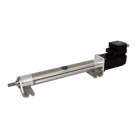
- Page 1 Original Line Electric Actuator, Motor, and Driver Quick Start Manual Please read this manual carefully before implementing your Original Line Electric Actuator...
-
Page 2: Table Of Contents
Original Line Electric Actuator, Motor, and Driver Quick Start Manual Contents 1. Actuator-only Models ..............2 Installing your motor 2. Actuator and Motor Models ............3 Motor specifications and wiring diagram 3. Actuator, Motor, and Driver Models ..........6 a. Mount your drive ..............6 b. Connect the DC power supply to the driver ...... -
Page 3: Actuator-Only Models
Congratulations on purchasing an Original Line Electric actuator from Bimba. Our OLE actuators are designed, built, and tested to provide the longest life, greatest durability, highest speed, and greatest thrust per dollar. We look forward to serving your electric actuator needs with the same responsiveness and engineering expertise you are accustomed to receiving for our pneumatic products. Every OLE actuator is backed by a one-year warranty. Extend it to a two- year warranty by registering on our website at www.bimba.com/pdf/OLEwarrantyregistration.pdf. 1. Actuator-only Models Installing your motor a. Remove plug to provide access to coupler. -
Page 4: Actuator And Motor Models
12 in-lbs. #10-24 35 in-lbs. d. Tighten coupler clamp screw so motor shaft is secured (refer to Table 1 for torque specification). The coupler clamps around the circumference of the motor shaft. The orientation of any flat on the shaft does not matter. Replace coupler access plug. Tighten the coupler clamp screw to the torque value in Table 1. 2. Actuator and Motor Models Orange Orange Blk/Wht All Bimba step motors use the same Org/Wht 8-wire wiring color code convention, as Org/ Blk/Wht shown below. Black Warning: Be sure power is off before Black connecting or disconnecting the motor. Yellow Red/... - Page 5 If you have ordered your actuator with a motor/encoder combination, the encoder specifications are listed in Table 4. Table 4 Encoder Specifications 17 and 23 Frame Motors 34 Frame Motor Power Input 5 V DC, 100 mA Max. 5 V DC, 160 mA Resolution 2048 pulses per rev. 2000 pulses per rev. Output High 2.4 V DC Min. 2.5 V DC Min.
- Page 6 Encoder connections for the 34 frame stepper are identified in Table 6. The cable provided has flying leads which can be connected to your controller. Table 6 Pin No. Wire Color Function Yellow Channel A Yellow/White Channel A- Blue Channel B Blue/White Channel B- Orange Index Orange/White Index- Green Green/White Brown Not used Brown/White White Gray/White +5 V DC input power Black Encoder ground Gray Drain/shield...
-
Page 7: Actuator, Motor, And Driver Models
• Wires - 18 to 20 gage recommended • Wire cutter/stripper • An appropriate DC power supply. Warning: Do not apply power until all connections are made. The DRV-4 accepts power supply voltages from 24 to 48 VDC, while the DRV-8 accepts power supply voltages from 24 to 75 VDC. The current demand will never exceed double the motor current (see Table 3, Amps column). However, the DRV will convert a high voltage low current power supply into a lower voltage higher current power supply. A 24V 4A supply will perform similarly to a 48V 2A supply. Use Table 7 below as a guideline. Use unregulated power supplies without overvoltage protection to avoid problems with regeneration during rapid deceleration. Table 7 Driver Power Bimba Parallel Parallel 24V Power 48V Power Supply Motor Current Current Supply Supply Amps per Voltage Draw Draw Max. -
Page 8: Connect The Dc Power Supply To The Driver
Warnings: • Do not install where ambient air is more than 104° F. • Do not install where there is no air flow • Do not install where drive can get wet. • Do not install where electrically conductive material can fall on the driver. • Drives must be mounted at least one-half inch apart. b. Connect the DC power supply to the driver -- Do not apply power Warning: Observe proper polarity when connecting wires. I. Make sure the power supply is not on. Connect V+ and V- from the power supply to the V+ and V- terminals of your driver. II. Ensure a proper earth ground connection by using the screw on the left side of the chassis. If using an external fuse, we recommend the following in-line with the V+ connection: DRV-4: 3AG, 4 amp (Littlefuse 313004P) DRV-8: 3AG, 6.25 amp (Littlefuse 3136.25P) -
Page 9: Set Rotary Switch For Motor Selected
Set rotary switch for the motor selected (This is normally set by the factory for the motor specified.) Turn the rotary switch to the number that represents the motor you have. This sets current and anti- resonance settings for optimum performance. Bimba Motor Option Code Setting Frame 17 frame P1, E1, Y1, Z1... -
Page 10: Set Load Inertia
f. Set load inertia Switch 3 chooses between • Values are multiples of rotor two load inertia ranges. inerta (see Table 3) • Use 0-4x for smaller leads and This information is used in the shorter strokes (factory default) anti-resonance configuration. • Use 5-10x for longer leads and greater loads • 5-10x may reduce performance. 5-10X 0-4X g. Select step resolution There are 4 microstep resolutions to choose from as well as full and help step • 200 • 200µ (microstep emulation) factory default 5 6 7 5 6 7... -
Page 11: Apply Power And Run Self Test
Microstepping provides smoothest rotation. However, a faster step pulse rate (frequency) is required for a given RPM as shown in Table 8 below. Table 8 Pulses per Degrees per Pulse frequency re- Pulse frequency re- revolution step quired for 300 RPM quired for 3000 RPM 1,000 Hz 10,000 Hz 2,000 Hz 20,000 Hz 2000 0.18 10,000 Hz 100,000 Hz 5000 0.072 25,000 Hz 250,000 Hz 12800... - Page 12 Connection Examples: STEP & DIR DIR- Indexer DIR+ with Sourcing STEP- Outputs STEP STEP+ Connecting to indexer with Sourcing Outputs +5V OUT DIR+ Indexer DIR- with Sinking STEP+ Outputs STEP STEP- Connecting to Indexer with Sinking Outputs DIR+ DIR+ Indexer DIR- DIR- with...
- Page 13 Connection Examples: EN The 5-24 V EN input disables power to the motor. 5-24 switch or relay Power (closed=logic low) Supply Connecting an Input to a Switch or Relay 5-24 Power OUT+ Supply OUT– Connecting another drive to EN (When output closes, input closes) 12-24 Power output...
-
Page 14: Fault Output
j. FAULT output The DRV drives feature a digital FAULT output. This output closes to signal a fault condition. This output can be used to drive LEDs, relays and the inputs of other elec- tronic devices like PLCs. The “+” (collector) and “-” (emitter) terminals of the output transistor are available at the connector. This allows you to configure the output for current sourcing or sinking. Diagrams of each type of connec- tion follow. Do not connect the output to more than 30 VDC. The current through the output terminal must not exceed 80 mA. 5-24 VDC 5-24 VDC Power Supply Power Supply – –... -
Page 15: Set Step Pulse Type
k. Set step pulse type Most indexers and motion controllers provide motion commands in the “Step and Direction” format. The Step signal pulses once for each motor step and the direction signal commands direction. However, a few PLCs use a differ- ent type of command signal: one signal pulses once for each desired step in the clockwise direction (called STEP CW), while a second signal pulses for counterclockwise motion (STEP CCW). The drives can accept this type of signal if you remove the cover and move jumper S3 from the “1-2” position to the “1-3” position. Factory default is the 1-2 position. As you can see in the image, the jumper terminals (2, 1, 3) and S3 and S4 designators are printed in white on the circuit board. Jumper S4: noise filter Jumper S3: step pulse type Shown in 1-2 position Shown in 1-2 position l. Step pulse noise filter Electrical noise can cause the drive to think that one step pulse is two or more pulses, resulting in extra motion and inaccurate motor and load posi- tioning. To combat this problem, the drive includes a digital noise filter on the STEP and DIR inputs. The default factory setting of this filter is 150 kHz. -
Page 16: Technical Specifications
m. Technical specifications Amplifier Digital MOSFET. 20 kHz PWM. Suitable for driving two phase and four phase step motors with four, six or eight leads. Supply voltage: DRV-4 24-48 VDC Under voltage alarm: 20 VDC Over voltage shutdown: 60 VDC DRV-8 24-75 VDC Under voltage alarm: 20 VDC Over voltage shutdown: 85 VDC Motor current: 0.5 to 7.8 amps/phase peak of sine (DRV8) 0.25 to 4.5 amps/phase peak of sine (DRV4) Digital Inputs Optically isolated, 5 - 24V logic. Sourcing, sinking or differential signals can be used. -
Page 17: Alarm Codes
n. Alarm codes In the event of a drive fault or alarm, the green LED will flash one or two times, followed by a series of red flashes. The pattern repeats until the alarm is cleared. Code Error solid green no alarm, motor disabled flashing green no alarm, motor enabled flashing red configuration or memory error 1 green, 4 red power supply voltage too high 1 green, 5 red over current / short circuit 1 green, 6 red open motor winding 2 green, 3 red internal voltage out of range 2 green, 4 red power supply voltage too low... -
Page 18: Troubleshooting Guide And Faq
If windings are shorted, the motor must be replaced. Problem: Actuator operation is stiff, seems to be binding. Solution: Check for dents on the body tube, motor end bell, and dam- age to the square rod. If there are signs of visible damage, the actuator or motor or both may need to be replaced. Dents on the motor shaft or endbells may cause the rotor to seize or rub, producing binding and stiff operation. While the nut of the OLE actuator is self-lubricating, rod lubri- cations is recommended at regular intervals. Use Bimba HT-99 grease. Problem: Can I use switches with my OLE for end of stroke sensing? Solution: All OLE actuators have magnetic pistons. OLE actuators can use the same switches as Original Line pneumatic cylinders. Refer to the Bimba catalog for switch recommendations. Problem: The motor gets hot. Solution: Step motors tend to run hot (the actual maximum case tem- perature is 80° C). However, the motor should not get too hot to touch. If it is overheating, the drive current may be set too high. All standard OLE step motors are 8-wire motors. Refer to Table 3 in this manual for... - Page 19 Problem: The motor (actuator) oscillates back and forth at low speeds. Solution: This is due to resonance, common between 1-4 rps. If this is observed with no load, add a load to the motor (the load will dampen out resonance). Changing from full-step to half-step or microstepping will also solve resonance problems. Step and Direction Drives Note: Please read your manual first before and during your setup. Bimba manuals, available at www.bimba.com/OLE/manuals, are short, to the point, and comprehensive. Problem: The drive’s power LED does not illuminate when power is ap- plied. Solution: Check the fuse and replace if necessary with one of the extra fuses included with your drive. If you have no fuses or continuously blow fuses, call Bimba Technical Support. Check your power supply to be sure it is not providing an excessively high voltage to the drive.
- Page 20 Problem: The motor does not move when a step signal is sent to the drive. Solution: If the enable input is on (low with respect to a 5-24 volt signal), it will disable the motor. Do not connect anything to the enable input if there is no reason to disable the motor. Problem: The motor will not run slow enough with a potentiometer con- nected to my drive (it has an internal oscillator). Solution: Some drives’ internal potentiometers cannot be adjusted to zero speed. Check the specifications in the manual that came with the drive. Problem: At startup, the motor does not run although the wiring is cor- rect. Solution: Make sure that dip switches and jumpers are set properly. Read your driver manual carefully. Problem: System not working properly. Solution: Troubleshoot by replacing the drive and see if the problem persists. Please read your drive manual before and during your setup. Bimba manuals, concise and comprehensive, are available for download at our website, www.bimba.com.
- Page 21 Bimba Manufacturing Company Monee, Illinois 60449-0068 Tel: 708.534.8544 Tech Support: 800.44BIMBA Fax: 708.235.2014 support@bimba.com www.bimba.com Manual OLE-410 Effective April 2010...
Need help?
Do you have a question about the OLE Series and is the answer not in the manual?
Questions and answers