
Related Manuals for Optimum DPA 22


Summary of Contents for Optimum DPA 22
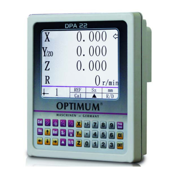
- Page 1 OPTIMUM M A S C H I N E N - G E R M A N Y Operating manual Version 1.0 Digital position display DPA 22...
-
Page 2: Table Of Contents
OPTIMUM M A S C H I N E N - G E R M A N Y Table of contents Safety Safety instructions ............................4 1.1.1 Safety and warranty informations ......................4 Intended use .............................4 Identification of danger and notes......................4 1.3.1 Danger classes ............................4 Target group .............................5... - Page 3 Dear customer, Thank you very much for purchasing a product made by OPTIMUM. OPTIMUM metal working machines offer a maximum of quality, technically optimum solutions and convince by an outstanding price performance ratio. Continuous enhancements and product innovations guarantee state-of-the-art products and safety at any time.
-
Page 4: Safety
Warranty can only be claimed for components supplied by Optimum Maschinen Germany GmbH. If display is used together with other products, the warranty for the complete sys- tem is invalid. -
Page 5: Target Group
OPTIMUM M A S C H I N E N - G E R M A N Y Target group Installation instructions and user manual are intended for the engineering, commissioning and installation personnel of plant or machine manufacturers. This group needs profound knowl- edge of an position indicator's necessary connections of a electronic display and its integration into a complete machinery. -
Page 6: Installation
OPTIMUM M A S C H I N E N - G E R M A N Y Installation Scope of delivery Digital position display Fixture External power supply Speed sensor, without commercial permanent magnets as a signal transducer... -
Page 7: Electrical Installation
OPTIMUM M A S C H I N E N - G E R M A N Y Electrical installation WARNING! Destruction of parts of equipment and loss of regulation control Check all line connections and plug connections before switching on supply voltage. -
Page 8: Power Supply Speed Sensor
OPTIMUM M A S C H I N E N - G E R M A N Y Power supply speed sensor Power is supplied via the rear jack plug . Connect the sensor for speed measurement from the scope of delivery with the electronic display. -
Page 9: Reader Signal Plug Pinout
1 Volt) or a TTL differential (TTL square wave) signal. We recommend the application of original measuring gibs and magnetic measuring systems from OPTIMUM. If the digital display is to be operated with measuring devices from other manufacturers, pay attention that this measuring gib provides an output signal of one of the two signal types and the pin assignment is consistent with the following table. -
Page 10: Installation Of Magnetic Sensor And Magnetic Strip
For technical reasons the strip should be approx. 30mm longer than the actual measuring dis- tance. ATTENTION! For an optimum of adhesion, all anti-adhesive substances (such as oil, grease, dust etc.) must be removed by using residue-free (=evaporating) cleaners. Suitable cleansing agents are e.g. ketones (acetone) or alcohols; Messrs.octite and 3M can both supply such cleansing liquid. -
Page 11: Installation Examples
OPTIMUM M A S C H I N E N - G E R M A N Y Secure the overlapping ends of the cover against detachment . ATTENTION! Do not expose the system to magnetic fields. Any direct contact of the magnetic strip with magnetic fields (e.g. -
Page 12: Necessary Measures
OPTIMUM M A S C H I N E N - G E R M A N Y Cable outlet Travel direction Sensor Counting direc- tion negative Img.2-5: Definition of counting direction Distance measurements between sensor and magnetic tape and angular tolerances, must ... -
Page 13: Trouble Shooting
Blank Shielding NOTE ! The following statements describe the procedure for attachment of OPTIMUM ML-type absolute measuring glass scales. Please follow the installation instructions and requirements accompanying the given component when installing incrementally measuring magnetic measurement systems from OPTIMUM, or for measurement systems from third-party manufacturers. -
Page 14: Assembly Of The Measurement Gib Housing
OPTIMUM M A S C H I N E N - G E R M A N Y 2.7.1 Assembly of the measurement gib housing Before mounting it on the machine, check the operability of the measuring gauges. To do so, use the digital position indicator or a similar device. -
Page 15: Trouble Shooting
OPTIMUM M A S C H I N E N - G E R M A N Y Check the orientation of the reading head using a dial gauge. The parallel error between the orthogonal side surfaces of the measuring gib and the ... -
Page 16: Operation
OPTIMUM M A S C H I N E N - G E R M A N Y Operation The device's display is in the default state when initially turned on. Parameter settings Press button for 3 seconds to access parameter settings. -
Page 17: Parameter Meanings
OPTIMUM M A S C H I N E N - G E R M A N Y 3.1.1 Parameter meanings Meanings of parameters and settings. Accuracy of representations on the display When a higher representational accuracy value is set on the display than the actual counting resolution, the representational accuracy value will be shown accordingly. - Page 18 OPTIMUM M A S C H I N E N - G E R M A N Y When a higher representational accuracy value is set on the display than the actual counting resolution, the representational accuracy value will be shown accordingly.
-
Page 19: Description Of The Keys
OPTIMUM M A S C H I N E N - G E R M A N Y Description of the keys Sign on the key Name of the key Function description X axis key To select the X coordinate axis... - Page 20 OPTIMUM M A S C H I N E N - G E R M A N Y For display of the Z+Z0 value Z+Z0 key (3 axes) Z and Z0 are added For internal parameter settings Programming key ...
-
Page 21: Reference Marker Function
OPTIMUM M A S C H I N E N - G E R M A N Y Reference marker function Set a zero point with preset axis values Set a relative coordinate system based on current machine position ... -
Page 22: Calculator Function
OPTIMUM M A S C H I N E N - G E R M A N Y Calculator function Add, subtract, multiply and divide. Press button to start the calculator. The display shows . The number field for the rotational speed indicator is used as input- and result field. -
Page 23: Coordinate Points Along A Diagonal Line
OPTIMUM M A S C H I N E N - G E R M A N Y Coordinate points along a diagonal line Creates a line within a coordinate system, along which a specified number of uniformly spaced coordinate points are defined. - Page 24 OPTIMUM M A S C H I N E N - G E R M A N Y Number of coordinate points: Input the number of coordinate points using the numeric keys and confirm with the key. Press the button to execute the function.
-
Page 25: Coordinate Points On A Circle Or Arc
OPTIMUM M A S C H I N E N - G E R M A N Y Coordinate points on a circle or arc Creates a circle or arc within a coordinate system, along which a specified number of uniformly spaced coordinate points are defined. - Page 26 OPTIMUM M A S C H I N E N - G E R M A N Y Midpoint of the circle or arc: Input the midpoint of the arc on the coordinate plane using the numeric keys and confirm with key.
- Page 27 OPTIMUM M A S C H I N E N - G E R M A N Y The display shows: Press the button to query the individual coordinate points Positioning to coordinate points: Press button to select the desired coordinate point.
-
Page 28: Inclined Plane
OPTIMUM M A S C H I N E N - G E R M A N Y Inclined plane Creates an inclined plane in a coordinate system such that processes can be carried out on said inclined plane. ... - Page 29 OPTIMUM M A S C H I N E N - G E R M A N Y Press the button to execute the function. The display shows: Positioning to a coordinate point on the inclined plane: The machine axes will proceed until the positions of the selected coordinate plane read 0.000.
-
Page 30: Arc
OPTIMUM M A S C H I N E N - G E R M A N Y Creates an arc in a coordinate system such that processes can be carried out on said arc. Press button to access parameter settings. Press the button again to exit from parameter settings. - Page 31 OPTIMUM M A S C H I N E N - G E R M A N Y Midpoint of the arc: Input the midpoint of the arc on the coordinate plane using the numeric keys and confirm with key.
- Page 32 OPTIMUM M A S C H I N E N - G E R M A N Y The display shows: Positioning to coordinate points: The coordinates of the first point of the coordinate plane are shown. The machine axes will proceed until the positions on the selected coordinate plane read 0.000.
-
Page 33: Tool Data Function
OPTIMUM M A S C H I N E N - G E R M A N Y 3.10 Tool data function Creates up to 99 tool data sets in relation in the coordinate system. Usage of the tool data function makes it possible to establish a specific relationship between the tool data in the coordinate system and the displayed values. -
Page 34: Appendix 4.1 Copyright
- Non reproducible software errors Any services, which OPTIMUM GmbH or one of its agents performs in order to fulfil any additional warranty are neither an acceptance of the defects nor an acceptance of its obli- gation to compensate. Such services do neither delay nor interrupt the warranty period. -
Page 35: Note Regarding Disposal / Options To Reuse
OPTIMUM M A S C H I N E N - G E R M A N Y Note regarding disposal / options to reuse: Please dispose of your machine in an environmentally friendly way, not by disposing of the waste not in the environment, but by acting in a professional way. - Page 36 Modified settings Experiences with DPA2000 / DPA2000S, which could be important to other users. Recurring failures Optimum Maschinen Germany GmbH Dr.-Robert-Pfleger-Str. 26 D-96103 Hallstadt Fax +49 ( 0 ) 951 - 96555 - 888 email: info@optimum-maschinen.de DPA22...
- Page 37 M A S C H I N E N - G E R M A N Y EC Declaration of Conformity according EMC Directive 2014/30/EC The manufacturer / Optimum Maschinen Germany GmbH distributor: Dr.-Robert-Pfleger-Str. 26 D - 96103 Hallstadt hereby declares that the following product...
- Page 38 OPTIMUM M A S C H I N E N - G E R M A N Y DPA22 Original operating instructions...
Need help?
Do you have a question about the DPA 22 and is the answer not in the manual?
Questions and answers