
Subscribe to Our Youtube Channel
Related Manuals for Optimum DPA 2000


Summary of Contents for Optimum DPA 2000
- Page 1 M A S C H I N E N - G E R M A N Y Operating manual Version 2.1.2 Digital position display DPA 2000/ DPA 2000S Keep for future reference! 15.6.11 Digital position display DPA 2000/ DPA 2000S ; Version 2.1.2 Page 1...
-
Page 2: Table Of Contents
Display Z+Z0 value (3-axes) ................24 Metric/inch conversion ..................25 4.10 Function of the reference mark (zero position) of the reading device ....25 4.11 Calculator function ....................26 Page 2 Table of contents Digital position display DPA 2000/ DPA 2000S ; Version 2.1.2 15.6.11... - Page 3 Dimensions and mounting Troubleshooting Appendix Copyright ......................43 Warranty ....................... 43 Disposal ....................... 44 Product follow-up ....................44 EC Declaration of Conformity ................45 15.6.11 Table of contents Digital position display DPA 2000/ DPA 2000S ; Version 2.1.2 Page 3...
-
Page 4: Safety
The device is designed and manufactured to be used universally in environments where there is no potential danger of explosion. For the operation, additionally absolute or incremental measuring systems for the position acquisition are required. Page 4 Safety Digital position display DPA 2000/ DPA 2000S ; Version 2.1.2 15.6.11... -
Page 5: Invalid Modification Of The Device
We would like to emphasize that any modifications to the construction, or technical or technolo- gical modifications that have not been authorized by Optimum Maschinen Germany GmbH will also render the guarantee null and void. Possible dangers caused by machine tools The device is operated in immediate proximity of machine tools. -
Page 6: Additional Qualification Requirements
1.12 Accident report Inform your superiors and Optimum Maschinen Germany GmbH immediately in the event of accidents, possible sources of danger and any actions which almost led to an accident (near misses) that are connected with the digital position display and the machine tool. -
Page 7: General Instruction
Do not clean the cover using abrasive cleaning agents or agents which would change the surface of plastic materials; Clean the display window at the front side of the position display using an neutral and anti- statically acting cleaning agent. 15.6.11 Safety Digital position display DPA 2000/ DPA 2000S ; Version 2.1.2 Page 7... -
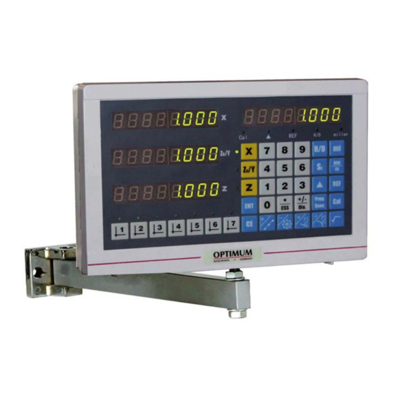
Page 8: The Front Panel And Rear Panel
The front panel and rear panel The front panel and a description of the keys Abb.2-1: DPA 2000S front side Page 8 The front panel and rear panel Digital position display DPA 2000/ DPA 2000S ; Version 2.1.2 15 / 06 / 2011... -
Page 9: The Rear Panel
Photo-elektrical input for schwitch Transducer for signal input Interface for data transfer Abb.2-3: DPA 2000S rear side 15 / 06 / 2011 The front panel and rear panel Digital position display DPA 2000/ DPA 2000S ; Version 2.1.2 Page 9... -
Page 10: Description Of The Keys
(the indicator light is located above it) Metric/Inch conversion The metric/inch conversion (the indicator light is located above it) Page 10 The front panel and rear panel Digital position display DPA 2000/ DPA 2000S ; Version 2.1.2 15 / 06 / 2011... - Page 11 To display the datum mark coordinates of The cutter 3 key cutter 3 (the indicator light is located above it) 15 / 06 / 2011 The front panel and rear panel Digital position display DPA 2000/ DPA 2000S ; Version 2.1.2 Page 11...
- Page 12 To display the datum mark coordinates of The cutter 7 key cutter 7 (the indicator light is located above it) Page 12 The front panel and rear panel Digital position display DPA 2000/ DPA 2000S ; Version 2.1.2 15 / 06 / 2011...
-
Page 13: Measuring Device - Pin Assignment At Dpa 2000
15 / 06 / 2011 The front panel and rear panel Digital position display DPA 2000/ DPA 2000S ; Version 2.1.2 Page 13... -
Page 14: Input/Output Connection
External switch common cable Low speed state External switch low speed signal Analog grounding AGND Transducer analog signal common terminal Page 14 The front panel and rear panel Digital position display DPA 2000/ DPA 2000S ; Version 2.1.2 15 / 06 / 2011... -
Page 15: Available Accessories (Only For Dpa 2000S)
Perforated disk for speed sensor, 3383927 lathes more largely D360 Magnetic tape MB 100 3383941 Read head activated 3383932 15 / 06 / 2011 The front panel and rear panel Digital position display DPA 2000/ DPA 2000S ; Version 2.1.2 Page 15... -
Page 16: Assembly And Commissioning
Measuring gauges are linear measuring systems which collect the position of mobile machine parts via a sensor and forward them coded to the position display. Page 16 Assembly and commissioning Digital position display DPA 2000/ DPA 2000S ; Version 2.1.2 15 / 06 / 2011... -
Page 17: Assembly Of The Reading Head
The following items are required in addition: ON/OFF switch to switch over between the manual speed setting and the cutting constant control 15 / 06 / 2011 Assembly and commissioning Digital position display DPA 2000/ DPA 2000S ; Version 2.1.2 Page 17... -
Page 18: Electrical Connection
If it is required to change over to manual speed setting an allpication module with two analog inputs will be additionally required. For programming data please refer to the attached manual. Page 18 Assembly and commissioning Digital position display DPA 2000/ DPA 2000S ; Version 2.1.2 15 / 06 / 2011... - Page 19 M A S C H I N E N - G E R M A N Y Wiring diagram to connect the DPA 2000S 15 / 06 / 2011 Assembly and commissioning Digital position display DPA 2000/ DPA 2000S ; Version 2.1.2 Page 19...
-
Page 20: Programming The Dpa 2000S
Switch over between the manual speed setting and the cutting constant control using the corres- ponding ON/OFF switch. The two switch settings need to be marked by the function markings which are being switched. Page 20 Assembly and commissioning Digital position display DPA 2000/ DPA 2000S ; Version 2.1.2 15 / 06 / 2011... -
Page 21: First Commissioning
Only switch on the device by using the main switch if the measuring gauges are con- nected and the power cord is connected to the electrical power supply. 15 / 06 / 2011 Assembly and commissioning Digital position display DPA 2000/ DPA 2000S ; Version 2.1.2 Page 21... -
Page 22: Description Of The Basic Operation
Z0/Y-axis, then press the key, delete the Z0/Y-axis; Press the key, select the Z-axis, then press the key, delete the Z-axis. Page 22 Description of the basic operation Digital position display DPA 2000/ DPA 2000S ; Version 2.1.2 15 / 06 / 2011... -
Page 23: Preset Current Coordinate Value Of The Axis
If the current positions of the Y or Z axes need to be preset, press the key in step (2). 15 / 06 / 2011 Description of the basic operation Digital position display DPA 2000/ DPA 2000S ; Version 2.1.2 Page 23... -
Page 24: Radius/Diameter Conversion Of The X-Axis
The actual position which is now dis- played for the X-axis is 20.000. Page 24 Description of the basic operation Digital position display DPA 2000/ DPA 2000S ; Version 2.1.2 15 / 06 / 2011... -
Page 25: Tool Data Function
Z0-axis will display "- - - - - - - - " , the Z-axis will display the sum for Z+Z0; Press the key again, and the Z- and Z0-axes go to the standard display. 15 / 06 / 2011 Description of the basic operation Digital position display DPA 2000/ DPA 2000S ; Version 2.1.2 Page 25... -
Page 26: Metric/Inch Conversion
0.000; Press the key, the REF indicator light turns off and the display returns to the standard display. Page 26 Description of the basic operation Digital position display DPA 2000/ DPA 2000S ; Version 2.1.2 15 / 06 / 2011... -
Page 27: Calculator Function
Number of holes to be divided (LNo. H): The number of points to divide the line segment to equal parts, n points to divide the line segment into n-1 equal segments. 15 / 06 / 2011 Description of the basic operation Digital position display DPA 2000/ DPA 2000S ; Version 2.1.2 Page 27... - Page 28 . And this is the position of the corresponding hole. Page 28 Description of the basic operation Digital position display DPA 2000/ DPA 2000S ; Version 2.1.2 15 / 06 / 2011...
-
Page 29: Dividing Hole On The Circle Function
The XY coordinate layer is the default layer. The position of the current coordinate is taken as the default center coordinates and 15 / 06 / 2011 Description of the basic operation Digital position display DPA 2000/ DPA 2000S ; Version 2.1.2 Page 29... - Page 30 The LEDs on the X-axis will display the last entered value of the end point angle. The last entered value will be displayed on the LEDs on the Y-axis. Page 30 Description of the basic operation Digital position display DPA 2000/ DPA 2000S ; Version 2.1.2 15 / 06 / 2011...
-
Page 31: Machining Along The Oblique Line Function
The LEDs on the X-axis display the last value of the angle of the inclined line. The last ente- red value will be displayed on the LEDs on the Y-axis. 15 / 06 / 2011 Description of the basic operation Digital position display DPA 2000/ DPA 2000S ; Version 2.1.2 Page 31... -
Page 32: Arc Machining Function
The axes that do not associate with the selected coordinate layer will not be displayed. Page 32 Description of the basic operation Digital position display DPA 2000/ DPA 2000S ; Version 2.1.2 15 / 06 / 2011... - Page 33 Repeat the above three steps to finish the entry of the two coordinates for the starting point; 15 / 06 / 2011 Description of the basic operation Digital position display DPA 2000/ DPA 2000S ; Version 2.1.2 Page 33...
- Page 34 Page 34 Description of the basic operation Digital position display DPA 2000/ DPA 2000S ; Version 2.1.2 15 / 06 / 2011...
- Page 35 While the function arc machining, the function can be interrupted by pressing the key return to the standard display except for the cases stated above. 15 / 06 / 2011 Description of the basic operation Digital position display DPA 2000/ DPA 2000S ; Version 2.1.2 Page 35...
-
Page 36: Internal Parameter Setting
The counting directions can be set as "0" or "1", the first value represents the positive counting whereas the last values represents the negative counting. the counting resolution of the X-axis Page 36 Internal parameter setting Digital position display DPA 2000/ DPA 2000S ; Version 2.1.2 15.6.11... - Page 37 When the external switch low speed signal is effective, the D/A will out- put the principal axis speed corresponding to 10 V , 10 V = max. rpm. 15.6.11 Internal parameter setting Digital position display DPA 2000/ DPA 2000S ; Version 2.1.2 Page 37...
-
Page 38: Setting The Cutting Linear Speed And The Workpiece Diameter
X-axis displays the current value of the work piece diameter (or radius). Page 38 Internal parameter setting Digital position display DPA 2000/ DPA 2000S ; Version 2.1.2 15.6.11... -
Page 39: Dimensions And Mounting
OPTIMUM Dimensions and mounting M A S C H I N E N - G E R M A N Y Dimensions and mounting 15.6.11 Dimensions and mounting Digital position display DPA 2000/ DPA 2000S ; Version 2.1.2 Page 39... -
Page 40: Troubleshooting
2. The position display is in a 2. Leave the deviation function range. deviating function range. Page 40 Troubleshooting Digital position display DPA 2000/ DPA 2000S ; Version 2.1.2 15.6.11... - Page 41 2. Reconnect the shielding wire to the formance of the wire between the reading device reading device. position display and the metal cover is well con- nected. 15.6.11 Troubleshooting Digital position display DPA 2000/ DPA 2000S ; Version 2.1.2 Page 41...
-
Page 42: Appendix 8.1 Copyright
V-belts, ball bearings, illuminants, filters, sealings, etc. Non reproducible software errors Any services which OPTIMUM GmbH or one of its agents performs in order to fulfill in the frame of an additional guarantee are neither an acceptance of the defects nor an accept- ance of its obligation to compensate. - Page 43 Please only throw discharged batteries in the collection boxes in shops or at municipal waste management companies. 15 / 06 / 2011 Appendix Digital position display DPA 2000/ DPA 2000S ; Version 2.1.2 Page 43...
-
Page 44: Disposal
RoHS , 2002/95/CE The sign on the product or on its packing indicates that this product complies with the European guideline 2002/95/EC . Page 44 Appendix Digital position display DPA 2000/ DPA 2000S ; Version 2.1.2 15 / 06 / 2011... -
Page 45: Product Follow-Up
Experiences with the DPA 2000S, which could be important to other users Recurring failures Optimum Maschinen Germany GmbH Dr.-Robert-Pfleger-Str. 26 D-96103 Hallstadt Fax +49 (0) 951 - 96822 - 22 E-Mail: info@optimum-maschinen.de 15 / 06 / 2011 Appendix Digital position display DPA 2000/ DPA 2000S ; Version 2.1.2 Page 45... -
Page 46: Ec Declaration Of Conformity
Responsible for documentation: Kilian Stürmer, Tel.: +49 (0) 951 96822-0 Address: Dr.-Robert-Pfleger-Str. 26 D - 96103 Hallstadt Kilian Stürmer (Manager) Hallstadt, 15.6.11 Page 46 Appendix Digital position display DPA 2000/ DPA 2000S ; Version 2.1.2 15 / 06 / 2011...
Need help?
Do you have a question about the DPA 2000 and is the answer not in the manual?
Questions and answers