Table of Contents
Advertisement
Quick Links
Advertisement
Table of Contents

Related Manuals for Agilent Technologies G3588-68015


Summary of Contents for Agilent Technologies G3588-68015
- Page 1 Agilent 990 Micro-GC PRO Extension Boards User Manual...
- Page 2 Notices Warranty Safety Notices © Agilent Technologies, Inc. 2019 No part of this manual may be reproduced in The material contained in this document is any form or by any means (including electronic provided “as is,” and is subject to being...
-
Page 3: Table Of Contents
Contents 1 Introduction Safety Information Information Operating instructions General safety precautions Spare parts availability Service availability Analytical Instruments sales offices Introduction 2 General Information Pre-Installation Requirements Environmental requirements Space requirements Micro-GC PRO Power source Micro-GC PRO Extension Boards Installation Inspection Unpacking Packing list... - Page 4 Standard Digital GC I/O Digital I/O Channels and Relay Outputs (8x) 4 Analog Extension Board Analog Extension Board Analog Extension Board Layout Analog Output Channels Board ID 5 Digital Extension Board Digital Extension Board Digital Extension Board Layout Digital I/O Power Supply Digital I/O Channels and Relay Outputs (8x) Board ID Micro-GC PRO Extension Boards User Manual...
-
Page 5: Introduction
Introduction Safety Information 6 Introduction 10 Micro-GC PRO Extension Boards User Manual... -
Page 6: Safety Information
Introduction Safety Information Safety Information Information In accordance with Agilent’s commitment to customer service and safety, these Micro-GC PRO Extension Boards and their accompanying documentation (NEN 5509) comply with the CE specifications and the safety requirements for electrical equipment for measurement, control, and laboratory use (CEI/IEC 1010-1). -
Page 7: General Safety Precautions
Introduction General safety precautions WARNING: Indicates dangerous voltage: terminals fed from the interior by a voltage exceeding Shock hazard 1000V must be so marked. WARNING: Indicates parts that may cause burns when touched Burn hazard ... - Page 8 Introduction General safety precautions • Disconnect the instrument from all power sources before removing protective panels to C AU T I O N avoid exposure to potentially dangerous voltages. • When it is necessary to use a non-original power cord plug, make sure the replacement cord adheres to the color-coding and polarity described in the manual and all local building safety codes.
-
Page 9: Spare Parts Availability
Introduction Spare parts availability Spare parts availability It is the policy of Agilent to provide operational spare parts for any instrument and major accessory for a period of five (5) years after shipment of the final production run of that instrument. -
Page 10: Introduction
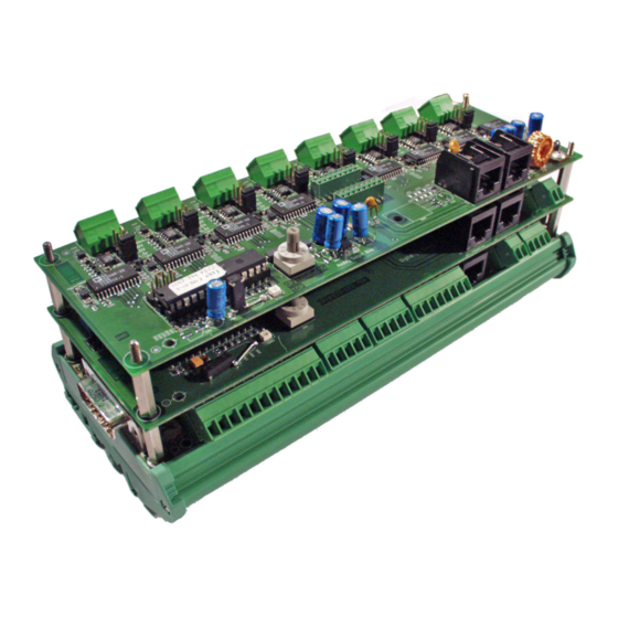
Introduction Introduction Introduction Figure 1. Micro-GC PRO Extension Boards Congratulations and thank you for purchasing the Micro-GC PRO Extension Boards. The Micro-GC PRO Extension Boards are used to provide the Micro-GC PRO additional in-outputs. For problems or questions about your Micro-GC PRO Extension Boards, please contact your NOTE nearest Agilent subsidiary or Agilent representative. -
Page 11: General Information
General Information Pre-Installation Requirements 12 Micro-GC PRO Extension Boards Installation 13 Shipping Instructions 17 Cleaning Instructions 18 Disposal Instructions 18 Extension Boards Concept 19 Housing and Mounting Options 20 Connect Basic Extension Board 21 Power Supply 22 Connecting Extension Boards 23 Micro-GC PRO Extension Boards User Manual... -
Page 12: Pre-Installation Requirements
General Information Pre-Installation Requirements Pre-Installation Requirements In order to assure a quick, safe and uncomplicated installation, we kindly request you make provisions as stated below before our Agilent service engineer will install your instrument(s). For more details please consult the Pre-Installation manual Micro-GC partnumber: CP501389. Environmental requirements •... -
Page 13: Micro-Gc Pro Extension Boards Installation
Check the packing list(s) to see if you have received all that you require. Packing list Table 1 Basic Extension Board (G3588-68015) Basic Extension Board (packed in anti-static bag) Extension Y-Cable, 40 pin to separated 25 pin Digital I/O and 15 pin Analog I/O connectors. - Page 14 General Information Packing list Table 2 Digital Extension Board (G3588-68017) Digital Extension Board (packed in anti-static bag) Small material: Screws x 4 Washer x 4 Standoff x 4 Nut x 4 Connector for board stacking Cable for boards interconnection 0.5 meter Package contents slip Micro-GC PRO Extension Boards User Manual...
- Page 15 General Information Packing list Table 3 Analog Extension Board (G3588-68016) Analog Extension Board (packed in anti-static bag) Small material: Screws x 4 Washer x 4 Standoff x 4 Nut x 4 Connector for board stacking Cable for boards interconnection 0.5 meter Package contents slip Micro-GC PRO Extension Boards User Manual...
- Page 16 General Information Packing list Table 4 Housing for extension boards (G3588-68018) Baseplate Side panels (2x) Small material: Screws x 4 Connector for board stacking Micro-GC PRO Extension Boards User Manual...
-
Page 17: Shipping Instructions
General Information Shipping Instructions Shipping Instructions If the Micro-GC PRO Extension Boards must be sent back to the factory, it is very important to follow the additional shipping instructions: Include all cables. NOTE Micro-GC PRO Extension Boards User Manual... -
Page 18: Cleaning Instructions
General Information Cleaning Instructions Cleaning Instructions To keep the Micro-GC PRO Extension Board’s surface clean, refer to the remarks given below: • Ensure the Micro-GC PRO Extension Boards are disconnected from the Micro-GC PRO and any other equipment before attempting to clean. •... -
Page 19: Extension Boards Concept
General Information Extension Boards Concept Extension Boards Concept The standard Micro-GC was developed to be used in combination with an external workstation that processes the data and controls external devices like relays, valves, etc. In the process-market, there is a strong need to add extra analog and digital I/O functions to the Micro-GC. -
Page 20: Housing And Mounting Options
General Information Housing and Mounting Options Housing and Mounting Options All extension boards are prepared to be mounted in a baseplate. (Table 4 on page 16) A standard DIN-rail is used to mount the baseplate on a flat underground. This makes it possible to stack all boards together onto one housing (with the Basic Extension Board mounted at the bottom) or to place each board in a separate housing (every extension board needing its own baseplate) and interconnect them via interconnection board cables. -
Page 21: Connect Basic Extension Board
General Information Connect Basic Extension Board Connect Basic Extension Board Be sure to switch the Micro-GC PRO off and remove the power cable before connecting any C AU T I O N cable. Use the included digital I/O and input cable to connect the Basic Extension Board to the Micro-GC PRO, as pictured in Figure 40-pin Digital/Analog Combined I/O Connector... -
Page 22: Power Supply
General Information Power Supply Power Supply All extension boards are powered by 12 volt DC. Two power supply options are possible: • 12 volt DC coming from the Micro-GC PRO. The maximum current is 500 mA (by electronic fuse). The maximum number of boards is three (3). •... -
Page 23: Connecting Extension Boards
General Information Connecting Extension Boards Connecting Extension Boards Extension boards contain parts that can be damaged by electrostatic discharge. Ensure you are properly grounded before handling. 1 To connect Analog or Digital Extension Boards on top of the Basic Extension Board replace the four corner screws with four standoff screws. - Page 24 General Information Connecting Extension Boards 3 Place the extension board carefully over the four standoffs. 4 Gently press on the connector (in the middle of the board) to ensure a good electrical connection with the Basic Extension Board. Standoff Figure 8. Connecting boards 5 Either secure the board with four nuts, or repeat this procedure to add another extension board.
- Page 25 Basic Extension Board Basic Extension Board 26 Basic extension board layout 27 Power supply 28 OHexternal power supply 29 1Hdigital I/O Power Supply 30 2Hstandard Analog GC Inputs 32 Standard Digital GC I/O 33 Digital I/O Channels and Relay Outputs (8x) 34 Micro-GC PRO Extension Boards User Manual...
-
Page 26: Basic Extension Board
Basic Extension Board Basic Extension Board Basic Extension Board Extension Boards contain parts that can be damaged by electrostatic discharge. Ensure you are properly grounded before handling. The Basic Extension Board contains the general Micro-GC I/O-signals, 8 opto-decoupled digital I/O lines, and 8 contact closure relays (contact rating: 0.5A-120VAC, 1A-30VDC or 0.15A-48VDC). -
Page 27: Basic Extension Board Layout
Basic Extension Board Basic extension board layout Basic extension board layout For detailed information on each part, click the links in the callouts. 15 Pole connector analog interface page 21 Standard analog GC inputs (0-10volt) page 34 LED, yellow, indicating communication with the Micro-GC Digital I/O... -
Page 28: Power Supply
Basic Extension Board Power supply Power supply Refer to Power Supply on page 22. Selection between the power sources must be done via jumpers on the Basic Extension Board. Factory set at 12 volt DC coming from the Micro-GC PRO. Figure 12. -
Page 29: Ohexternal Power Supply
Basic Extension Board OHexternal power supply OHexternal power supply The jumpers JP331 and JP332 (Figure 12 on page 28) are used to switch from 12 volt coming from he Micro-GC PRO and an external 12 volt voltage. Table 5 Power source jumpers Power source JP331 and JP332 jumpers 12 volt from Micro-GC PRO... -
Page 30: 1Hdigital I/O Power Supply
Basic Extension Board 1Hdigital I/O Power Supply 1Hdigital I/O Power Supply The digital I/O power supply is the voltage that is used for all digital I/O signals present on the Basic Extension Board. Table 6 Digital voltage I/O jumpers Digital voltage I/O possibilities JP451 and JP452 (jumper) + 12 volt (from Micro-GC PRO). - Page 31 Basic Extension Board 1Hdigital I/O Power Supply Figure 15. Schematic diagram of J400, J451 and J452 power connector Micro-GC PRO Extension Boards User Manual...
-
Page 32: 2Hstandard Analog Gc Inputs
Basic Extension Board 2Hstandard Analog GC Inputs 2Hstandard Analog GC Inputs Six (6) analog inputs are available for custom use. The input voltage range is 0-10 volts. When using the analog inputs, the Basic Extension Board needs to be connected to the Micro-GC PRO with the 15-pin analog input cable. -
Page 33: Standard Digital Gc I/O
Basic Extension Board Standard Digital GC I/O Standard Digital GC I/O The images below show the standard digital Micro-GC in and outputs. For more details, refer to the Micro-GC User Manual, chapter “external digital I/O”. Figure 17. Standard digital GC in/outputs Micro-GC PRO Extension Boards User Manual... -
Page 34: Digital I/O Channels And Relay Outputs (8X)
Basic Extension Board Digital I/O Channels and Relay Outputs (8x) Digital I/O Channels and Relay Outputs (8x) In addition to the standard GC I/O-lines, 8 extension digital I/O lines and 8 relays (contact rating: 0.5A-120VAC, 1A-30VDC or 0.15A-48VDC) are present on the Basic Extension Board. Each in/output channel (input or output status selectable by jumper) has a green LED indicating the state of the signal (low is “ON”... - Page 35 Basic Extension Board Digital I/O Channels and Relay Outputs (8x) LED (red) Digital output and relay status. LED (green) Digital I/O signal status. (low is “ON” or high is “OFF”) Figure 19. Digital I/O jumper, relay and LED Table 7 Digital in/output jumper Digital voltage I/O possibilities JP20X jumper...
- Page 36 Basic Extension Board Digital I/O Channels and Relay Outputs (8x) Figure 20. Schematic diagram of the digital in/outputs Figure 21. Schematic diagram of the relay output Micro-GC PRO Extension Boards User Manual...
- Page 37 Analog Extension Board Analog Extension Board 38 Analog Extension Board Layout 39 Analog Output Channels 40 Board ID 42 Micro-GC PRO Extension Boards User Manual...
-
Page 38: Analog Extension Board
Analog Extension Board Analog Extension Board Analog Extension Board Extension Boards contain parts that can be damaged by electrostatic discharge. Ensure you are properly grounded before handling. The Analog Extension Board contains 8 analog output channels. Each analog output channel generates an output voltage or current. -
Page 39: Analog Extension Board Layout
Analog Extension Board Analog Extension Board Layout Analog Extension Board Layout For detailed information on each part, click the links in the callouts. LED, yellow, indicating communication with the Micro-GC Board ID page 42 Analog output channels Board page 40 interconnection Board interconnection... -
Page 40: Analog Output Channels
Analog Extension Board Analog Output Channels Analog Output Channels Each analog output channel has his own connector, jumper, and LED. LED, red indicating that the current loop is not closed. Figure 24. Analog output channel Table 8 Analog outputs and jumpers Analog output JPXXX jumper Analog output... - Page 41 Analog Extension Board Analog Output Channels Figure 25. Schematic diagram analog output Micro-GC PRO Extension Boards User Manual...
-
Page 42: Board Id
Analog Extension Board Board ID Board ID Each of the connected extension boards must be set with a unique board address, selectable with the “Board ID” switch. The “0” position must not be used, as it is reserved for the Basic Extension Board. Figure 26. - Page 43 Digital Extension Board Digital Extension Board 44 Digital Extension Board Layout 45 Digital I/O Power Supply 46 Digital I/O Channels and Relay Outputs (8x) 48 Board ID 51 Micro-GC PRO Extension Boards User Manual...
-
Page 44: Digital Extension Board
Digital Extension Board Digital Extension Board Digital Extension Board Extension Boards contain parts that can be damaged by electrostatic discharge. Ensure you are properly grounded before handling. The Digital Extension Board contains 8 opto-decoupled digital I/O lines and 8 contact closure relays (contact rating: 0.5A-120VAC, 1A-30VDC or 0.15A-48VDC). -
Page 45: Digital Extension Board Layout
Digital Extension Board Digital Extension Board Layout Digital Extension Board Layout For detailed information on each part, click the links in the callouts. LED, yellow, indicating communication with the Micro-GC Board ID page 51 Analog output channels Board page 45 interconnection Board interconnection... -
Page 46: Digital I/O Power Supply
Digital Extension Board Digital I/O Power Supply Digital I/O Power Supply The digital I/O power supply is the voltage that is used for all digital I/O signals present on the Digital Extension Board. Figure 29. Digital voltage I/O jumpers Table 9 Power source jumpers Power source JP451 and JP452 jumper... - Page 47 Digital Extension Board Digital I/O Power Supply Figure 30. Schematic diagram of J400 power connector Micro-GC PRO Extension Boards User Manual...
-
Page 48: Digital I/O Channels And Relay Outputs (8X)
Digital Extension Board Digital I/O Channels and Relay Outputs (8x) Digital I/O Channels and Relay Outputs (8x) In addition to the standard GC and Basic Extension board I/O-lines, 8 extension digital I/O lines and 8 relays (contact rating: 0.5A-120VAC, 1A-30VDC or 0.15A-48VDC) are present on the Digital Extension Board. - Page 49 Digital Extension Board Digital I/O Channels and Relay Outputs (8x) Table 10 Digital in/output jumper Digital in/output JP20X jumper Digital input Digital output Default settings Micro-GC PRO Extension Boards User Manual...
- Page 50 Digital Extension Board Digital I/O Channels and Relay Outputs (8x) Figure 33. Schematic diagram of the digital in/outputs Figure 34. Schematic diagram of the relay output Micro-GC PRO Extension Boards User Manual...
-
Page 51: Board Id
Digital Extension Board Board ID Board ID Each extension board must have a unique board address selectable with the “Board ID” switch. The “0” position may not be used, as it is reserved for the Basic Extension Board. Figure 35. Board ID switch Micro-GC PRO Extension Boards User Manual... - Page 52 Agilent Technologies, Inc. 2019 First edition, October 2019 *G3588-90029* G3588-90029...