Advertisement
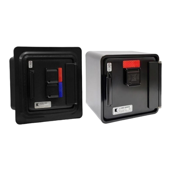
KNOXVAULT® 4400
TAMPER ALERT INSTALLATION INSTRUCTIONS
Door Tamper
Alert switch
(green wire)
Spacer shaft (2)
Rear Tamper
Alert switch hole
(B)
Backplate shown without housing for clarity
Adjust screw to
correct height so that
plunger is depressed
when door is closed
Tamper Alert switch
mounting screws (4)
Door Tamper Alert
switch (green wire)
KnoxVault
mounting holes (5)
Rear Tamper
Alert switch
(red wire)
Alarm wire
opening (A)
Rear Tamper Alert
switch hole (B)
All mounting holes
are 7/16" diameter (5)
Mounting holes
for key hooks (4)
Door Tamper Alert switch
mounting holes (2)
Alarm wire
opening (A)
Door Tamper Alert switch
1
2
Green Wires
to Security Alarm Panel
1601 W. DEER VALLEY ROAD, PHOENIX, AZ 85027
© Knox Company. All rights reserved.
Tamper Alert switch
mounting screws (4)
Rear Tamper
Alert switch
(red wire)
B
Adjust screw to correct height so
that plunger is depressed when
A
KnoxVault is mounted. Do not
bottom out Tamper Alert switch.
Alarm wire
opening (A)
Figure 1
A
Figure 2
INSIDE VIEW
B
A
Rear Tamper
Alert switch
mounting holes
(2)
Figure 3
Rear Tamper Alert switch
1
2
Red Wires
to Security Alarm Panel
Wiring Diagram
|
T.
800-552-5669
1. The KnoxVault 4400 Tamper Alert is designed to be
connected to an existing alarm system and should be
installed only by a qualified alarm technician.
2. Position KnoxVault on wall so wires from alarm panel
protrude into box through hole (A) in back plate. See
Figure 1, 2 and 3.
3. Bolt KnoxVault to wall, following directions provided in
mounting instructions.
IMPORTANT
Keep Tamper Alert switch hole (B) clear of caulk, debris
or other foreign material, otherwise the Tamper Alert
may not operate.
4. Door Tamper Alert switch: Screw the two spacer shafts
to screw holes, then screw door Tamper Alert to the end
of the spacer shafts with provided screws as shown in
Figure 1. (Door Tamper Alert switch used in both the Recess
and Surface Mount KnoxVault 4400.)
Rear Tamper Alert switch: Align rear Tamper Alert plunger
in back plate, hole (B), as shown in Figure 1. Check length
of plunger and, if necessary, adjust plunger screw to give
proper travel. Check plunger contact by GENTLY pressing
the bracket flush against the back plate. (Rear Tamper Alert
switch only used in the Surface Mount KnoxVault 4400.)
CAUTION
Do not bottom out Tamper Alert. If the rear Tamper Alert
adjustment screw protrudes too far, the rear Tamper Alert
switch will break when screws are tightened.
Use of an ohm meter is recommended to assure that switch
trips (0 ohms – for red/green wire, open for yellow wire)
when Tamper Alert switch is GENTLY pushed flush against
the back plate.
Secure the rear Tamper Alert switch to the back plate with
the provided screws.
5. Connect Tamper Alert wires to building alarm. Alarm wiring
must be pulled back through the alarm wire opening (A) to
prevent interference with door locking mechanism. Green
and Red wires must be secured tightly so that if box is
removed, wires will be broken in the process, thereby
causing alarm activation. In cases where yellow wires are
used, the yellow wires should be loosely secured so that if
box is removed, the wire can pull about an inch to allow the
Tamper Alert switch to close, causing an alert before the
wires break.
NOTES:
A. Electrical: maximum 24 V, 50 mA.
B. Red and Green wires indicate Normally Open (N.O.) Switch
(Closed when KnoxVault is secure)
C. Yellow wires indicate Normally Closed (N.C.) Switch
(Open when KnoxVault is secure)
|
F.
623-687-2290
|
INFO@KNOXBOX.COM
|
KNOXBOX.COM
OPE-KBSPEC-0091-C
Advertisement
Table of Contents

Related Manuals for Knox KnoxVault 4400


Summary of Contents for Knox KnoxVault 4400
- Page 1 KNOXVAULT® 4400 TAMPER ALERT INSTALLATION INSTRUCTIONS 1. The KnoxVault 4400 Tamper Alert is designed to be connected to an existing alarm system and should be Tamper Alert switch installed only by a qualified alarm technician. mounting screws (4) Rear Tamper Door Tamper 2.
Need help?
Do you have a question about the KnoxVault 4400 and is the answer not in the manual?
Questions and answers