Table of Contents
Advertisement
Quick Links
Advertisement
Table of Contents

Related Manuals for Calex PyroSigma Series


Summary of Contents for Calex PyroSigma Series
- Page 1 PyroSigma Series Operator’ s Guide...
-
Page 2: Specifications
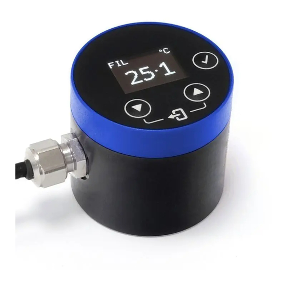
The PyroSigma is a fixed-mount sensor for measuring the temperature of a surface without contact. Its extremely small size makes it ideal for installation where space is restricted. The sensor works by detecting infrared energy that is emitted by the target object. The temperature is shown on the sensor’s built-in OLED display, and can be monitored continuously via the DC voltage output, e.g. -
Page 3: Installation
ACCESSORIES Accessories may be ordered at any time and added on-site. The following accessories are available: Fixed mounting bracket - Adjustable mounting bracket - Air purge collar OPTIONS Options are factory-installed and cannot be retrofitted. The following options are available: Certificate of Calibration - Extended cable INSTALLATION The installation process consists of the following stages:... -
Page 4: Electrical Interference
ELECTRICAL INTERFERENCE To minimise electromagnetic interference or ‘noise’, the sensor should be mounted away from motors, generators and such like. CABLE LENGTH Check the length of the cable run between the sensor and the measurement instrumentation. If necessary, the sensor can be ordered with a longer cable attached. Also, the cable can be extended using a shielded cable with 4 or more cores (3 if the alarm output is not used). -
Page 5: Air Purge Collar
AIR PURGE COLLAR The air purge collar is used to keep dust, fumes, moisture, and other contaminants away from the lens. It fits between the sensor and the mounting surface. Longer screws are provided for use with a panel or bracket at least 2 mm thick. Air flows into the hose barb fitting and out of the front aperture. -
Page 6: Power Supply
* A choice of indicating controllers, providing temperature display and relay outputs, is also available. Contact Calex for more information. Caution! Check the identification tags and ensure all wiring is correct before applying power to the sensor. -
Page 7: Operation
OUTPUT The temperature output is a voltage signal, measured between OP+ and PWR-. The output voltage is linear with measured temperature. The output voltage range is configurable in the sensor’s Settings menu. GROUNDING The sensor is tested to industrial standards for electromagnetic compatibility (EMC) as shown in Specifications. - Page 8 CONFIGURATION Menu Setting Description Emissivity Emissivity Enter the emissivity setting (between 0.2 and 1.0). The Setting emissivity setting should match the emissivity of the target surface. This can be determined experimentally by comparing measurements with a trusted contact probe, or estimated using an emissivity table. Non-reflective non-metals, such as rubber, foods, thick plastics, organic materials and painted surfaces, generally have a high emissivity, around 0.95.
- Page 9 Menu Setting Description Alarm Alarm Trigger The alarm is triggered if the temperature Output is higher than the Set Point. (continued) The alarm is triggered if the temperature is lower than the Set Point. Output Mode Active HI: In an alarm condition, the alarm wire AL will sink current to ground through the attached load (e.g.
-
Page 10: Lens Cleaning
In many cases, problems can be solved over the telephone. If the sensor is not performing as it should, try to match the symptom below to the problem. If the table does not help, call Calex for further advice. -
Page 11: Troubleshooting
TROUBLESHOOTING Symptom Probable Cause Solution No output or display No power to the Check the power supply and wiring sensor Inaccurate measured Target too small for Ensure the sensor’s view is completely filled temperature sensor’s field of view by the target. Position the sensor closer to the target to measure a smaller area. -
Page 12: Default Settings
Calex guarantees each instrument it manufactures to be free from defect in material and workmanship under normal use and service for the period of two years from the date of purchase. This guarantee extends only to the original buyer according to Calex’s standard Terms and Conditions of Sale.
Need help?
Do you have a question about the PyroSigma Series and is the answer not in the manual?
Questions and answers