peplink Pepwave AP One Series User Manual
For more information, please visit peplink.com
Hide thumbs
Also See for Pepwave AP One Series:
- User manual (57 pages) ,
- User manual (98 pages) ,
- User manual (59 pages)
Table of Contents
Advertisement
AP One Enterprise / AP One AC mini / AP One Rugged / AP One Flex / AP Pro AC
C
& T
OPYRIGHT
RADEMARKS
Specifications are subject to change without notice. Copyright © 2018 Pepwave Ltd. All Rights Reserved. Pepwave and the
Pepwave logo are trademarks of Pepwave Ltd. Other brands or products mentioned may be trademarks or registered trademarks of
their respective owners.
Pepwave AP One Series:
October 2018
Advertisement
Table of Contents

Related Manuals for peplink Pepwave AP One Series


Summary of Contents for peplink Pepwave AP One Series
- Page 1 Pepwave AP One Series: AP One Enterprise / AP One AC mini / AP One Rugged / AP One Flex / AP Pro AC October 2018 & T OPYRIGHT RADEMARKS Specifications are subject to change without notice. Copyright © 2018 Pepwave Ltd. All Rights Reserved. Pepwave and the Pepwave logo are trademarks of Pepwave Ltd.
-
Page 2: Table Of Contents
Table of Contents Introduction and Scope Product Features and Benefits Package Contents AP One Enterprise (APO-ENT) AP One AC mini (APO-AC-MINI) AP One Rugged (APO-RUG) AP One Flex (APO-FLX) AP Pro AC (APP-AGN3) Hardware Overview AP One Enterprise AP One AC mini AP One Rugged AP One Flex AP Pro AC... - Page 3 Settings System Tab Admin Security Firmware Time Event Log SNMP Controller Configuration Feature Add-Ons Reboot Tools > Ping Tools > Traceroute Tools > Nslookup Status Device Client List WDS Info Portal Rogue AP Event Log Restoring Factory Defaults Appendix Datasheets &...
-
Page 4: Introduction And Scope
Introduction and Scope Our AP Series of enterprise-grade 802.11ac/a/b/g/n Wi-Fi access points is engineered to provide fast, dependable, and flexible operation in a variety of environments, all controlled by an easy-to-use centralized management system. From the small but powerful AP One AC mini to the top-of-the-line AP Pro Duo our AP Series offers wireless networking solutions to suit any business need, and every access point is loaded with essential features such as multiple SSIDs, VLAN, WDS, and Guest Protect. -
Page 5: Product Features And Benefits
Product Features and Benefits Key features and benefits of AP Series access points: ● High-powered Wi-Fi transmitter enhances coverage and lowers cost of ownership. ● Independent security policies and encryption mechanisms for each virtual access point allow fast, flexible, cost-effective network builds. ●... -
Page 6: Package Contents
Package Contents AP One Enterprise (APO-ENT) 1x AP One Enterprise 1 x Mounting Bracket AP One AC mini (APO-AC-MINI) 1 x AP One mini 1 x 12V2A Power supply 1 x Mounting Bracket AP One Rugged (APO-RUG) 1 x AP One Rugged 1 x 12V2A Power supply 3 x 5dBi Omni Antenna ... -
Page 7: Hardware Overview
Hardware Overview AP One Enterprise Bottom View Top View Front View LED Indicators RED – Access point initializing Status GREEN – Access point ready OFF – No device connected to Ethernet port BLINKING – Ethernet port sending/receiving data LAN 1 ON –... -
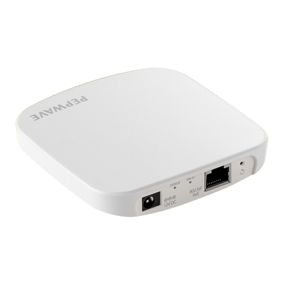
Page 8: Ap One Ac Mini
AP One AC mini F ront View Rear Panel View LED Indicators RED – Access point initializing Status GREEN – Access point ready OFF – 2.4/5GHz Wi-Fi radio off BLINKING – AP sending/receiving data Wi-Fi GREEN – 2.4/5GHz Wi-Fi radio on Note that this model includes a 2.4GHz Wi-Fi radio and a 5GHz Wi-Fi radio that can operate simultaneously to increase speed and reduce interference. -
Page 9: Ap One Rugged
AP One Rugged F ront View Rear Panel View LED Indicators On – Power On Power OFF – Power Off RED – Access point initializing Status GREEN – Access point ready OFF – 2.4/5GHz Wi-Fi radio off BLINKING – AP sending/receiving data Wireless GREEN –... -
Page 10: Ap One Flex
AP One Flex F ront View Rear Panel View Connector Panel (Inside the Lid) LED Indicators RED – Access point initializing Status GREEN – Access point ready OFF – No device connected to Ethernet port BLINKING – Ethernet port sending/receiving data ON –... -
Page 11: Ap Pro Ac
AP Pro AC F ront View Top/Bottom View & T OPYRIGHT RADEMARKS Specifications are subject to change without notice. Copyright © 2018 Pepwave Ltd. All Rights Reserved. Pepwave and the Pepwave logo are trademarks of Pepwave Ltd. Other brands or products mentioned may be trademarks or registered trademarks of their respective owners. -
Page 12: Installation
Installation Your access point acts as a bridge between wireless and wired Ethernet interfaces. A typical setup follows: Installation Procedures 1. Connect the Ethernet port on the unit to the backbone network using an Ethernet cable. The port should auto sense whether the cable is straight-through or crossover. 2. - Page 13 3. Wait for the status LED to turn green. 4. Connect a PC to the backbone network. Configure the IP address of the PC to be any IP address between 192.168.0.4 and 192.168.0.254, with a subnet mask of 255.255.255.0. 5. Using your favourite browser, connect to h ttps://192.168.0.3...
-
Page 14: Dashboard
Dashboard The D ashboard section contains a number of displays to keep you up-to-date on your access point’s status and operation. Remote assistance can also be turned off here, if it has been enabled. & T OPYRIGHT RADEMARKS Specifications are subject to change without notice. -
Page 15: General
General This section contains WAN status and general device information. When your access point is connected to a WAN, this field displays the WAN IP IP Address address. For more information, click the D etails l ink which shows connection type details This field displays the current WAN connection status. - Page 16 This section displays a variety of information about your wireless network. AP Status Wireless Network This field displays your access point’s SSID. SSID The radio frequency currently used by your access point appears here. If you’re using Radio the AP One AC mini or the AP One In-Wall and have configured both radios, this displays both radios in use.
- Page 17 value of 0 indicates that a VLAN ID is not being used. Your access point’s MAC address appears here. If you’re using the AP One AC mini MAC Address and have configured both radios, this displays a MAC address for both the 2.4GHz and (BSSID) 5GHz radio.
-
Page 18: Network
Network The settings on the N etwork tab control WAN and LAN settings, as well as allow you to set up PepVPN profiles. This section provides basic and advanced WAN settings. Basic Keep Default IP When enabled, this option maintains 1 92.168.0.3 as your access point’s IP address. IP Address Mode... - Page 19 Advanced This field specifies the VLAN ID to tag to management traffic, such as AP-to-AP Management controller communication traffic. The value is 0 by default, meaning that no VLAN tagging VLAN ID will be applied. NOTE: change this value with caution as alterations may result in loss of connection to the AP controller.
-
Page 20: Lan
This section offers a variety of settings that affect your access point’s operation on the LAN, such as settings for DHCP, DMZ, and port forwarding. Note that the following settings will be available only when your access point is operating in router mode. IP Settings IP Address Enter the LAN IP address and subnet mask to assign to your access point on the LAN. - Page 21 192.168.1.200 , with 24-bit subnet mask. Broadcast Enter the broadcast address that DHCP clients will use when communicating with the Address entire LAN segment. The default value is 1 92.168.1.255 . Enter the default gateway address that DHCP clients will use to access the internet. By Gateway default, this address will be the same as your access point’s IP address on the LAN.
- Page 22 The I P Protocol setting, along with the P ort setting, specifies the protocol of the service as TCP, UDP, ICMP, or IP. Traffic that is received by your access point via the specified protocol at the specified port(s) is forwarded to the LAN hosts specified by the S ervers setting.
-
Page 23: Interfaces > Ethernet Port
Interfaces > Ethernet Port Assign one (or more) specific VLAN(s) to one of the LAN ports. Configure the port as Access- or Trunk-port . For Trunk port, enter multiple VLAN IDs for VLAN filtering (e.g. 1,5-8,10) or keep the field empty for accepting all VLANs. For Access port, only single VLAN ID is supported. - Page 24 Once you’ve specified a local ID, click the N ew Profile button to configure PepVPN. PepVPN Profile Settings Enable Check this box to enable PepVPN. Enter a name to represent this profile. The name can be any combination of Name alphanumeric characters (0-9, A-Z, a-z), underscores (_), dashes (-), and/or non-leading/trailing spaces ( ).
- Page 25 unique peer ID number in the R emote ID field. This optional field becomes available when P re-shared Key is selected as the VPN Authentication method, as explained above. P re-shared Key defines the pre-shared key used for this particular VPN connection.
-
Page 26: Wireless Ssid
Use the controls on the A P tab to set the wireless SSID and AP settings, as well as wireless distribution system (WDS) settings. Wireless SSID Wireless network settings, including the name of the network (SSID) and security policy, can be defined and managed in this section. - Page 27 Available only on the AP One AC mini, this setting, shown below, allows you to enable or disable either of the two on-board radios. Radio Selection This setting, shown below, allows you to reduce 2.4 GHz band overcrowding, AP with band steering steers clients capable of 5 GHz operation to 5 GHz frequency.
- Page 28 Refers to the second layer in the ISO Open System Interconnect model. Layer 2 Isolation hWhen this option is enabled, clients on the same VLAN, SSID, or subnet are isolated to that VLAN, SSID, or subnet, which can enhance security. Traffic is passed to upper communication layer(s).
- Page 29 Choose v 1 or v 2 of the 802.1x EAPOL. When v 1 is selected, both v1 and v2 clients can associate with the access point. When v 2 is selected, only v2 clients can associate with 802.1X Version the access point.
- Page 30 Captive Portal Login Captive Portal Select E nable to turn on your access point’s built-in captive portal functionality. Authentication Choose O pen Access to allow users to connect without authentication or R ADIUS to require authentication.
- Page 31 Concurrent Login Check this box to allow users to have more than one logged in session active at a time. Enter a value in minutes to limit access time on a given login or enter 0 to allow Access Quota unlimited use time on a single login.
- Page 32 RADIUS Server Settings Enter the IP address of the primary RADIUS server and, if applicable, the secondary Host RADIUS server. Enter the RADIUS shared secret for the primary server and, if applicable, the secondary Secret RADIUS server. Authentication Enter the UDP authentication port(s) used by your RADIUS server(s) or click the Port Default...
- Page 33 Guest Protect Block LAN Check this box to block access from the LAN. Access To specify a subnet to block, enter the IP address and choose a subnet mask from the Custom Subnet drop-down menu. To add the blocked subnet, click .
- Page 34 Enter a value in kbps to limit the wireless network’s downstream bandwidth. Downstream Limit Enter 0 to allow unlimited downstream bandwidth. Client Upstream Enter a value in kbps to limit connected clients’ upstream bandwidth. Limit Enter 0 to allow unlimited upstream bandwidth. Client Enter a value in kbps to limit connected clients’...
- Page 35 fields will vary. Choose T CP or U DP from the P rotocol drop-down menu to allow or deny traffic using either of those protocols. From the P ort drop-down menu, choose A ny Port to allow or deny TCP or UDP traffic on any port.
-
Page 36: Settings
ARP Request Control A R P request control is a Broadcast filter feature which: ● blocks all broadcast traffic, ● relays DHCP requests, ● responds to ARP requests asking the MAC address of the gateway Default handling Choose between B ypass or D rop (default Bypass) Add IP/ MAC address pairs to this field to either: REPLY ... - Page 37 AP Settings Choose 8 02.11ng or 8 02.11n/ac as your access point’s Wi-Fi protocol. The AP One AC mini provides the 8 02.11ng protocol for the 2.4 GHz band and the Protocol 802.11n/ac protocol for the 5GHz band, as shown below. This drop-down menu specifies the national / regional regulations the AP should follow.
- Page 38 US. All US models are fixed to US channels only. This option defines which channel width the radio will use: 20MHz - Supports clients with 20MHz capability. This is the default value for 802.11ng. 40MHz - Supports clients with 20/40MHz capability. 20/40MHz...
- Page 39 transmits. The default value is 9 μ s . Set the wait time to receive an acknowledgement packet before retransmitting. The ACK Timeout default value is 4 8 μ s . Frame With this feature enabled, throughput will be increased by sending two or more data Aggregation frames in a single transmission.
-
Page 40: Wds
This setting specifies the time, in milliseconds, that your access point scans any Scanning Time particular channel while searching for nearby networks. Scheduled Radio Click C ustom Schedule to specify radio availability schedule options or select A lways Availability On... -
Page 41: System Tab
Admin Security Admin Settings This field allows you to define a name for this Peplink Balance unit. Devicer Name By default, D evice Name is set as M odel_XXXX , where X XXX refers to the last 4 digits of the serial number of that unit. -
Page 42: Firmware
Name Admin This field allows you to specify a new administrator password. Password Confirm Admin This field allows you to verify and confirm the new administrator password. Password A web login session will be logged out automatically when it has been idle longer than the Web Session Web Session Timeout Timeout... -
Page 43: Time
Do not disconnect the power during firmware upgrade process. Do not attempt to upload a non-firmware file or a firmware file that is not supported by Peplink. Upgrading the Peplink Balance with an invalid firmware file will damage the unit and may void the warranty. -
Page 44: Event Log
Port: Default 514 SNMP SNMP or simple network management protocol is an open standard that can be used to collect information about the Peplink Balance unit. SNMP configuration is located at S ystem>SNMP . & T OPYRIGHT RADEMARKS Specifications are subject to change without notice. - Page 45 SNMP Settings SNMP Device This field shows the router name defined at S ystem>Admin Security . Name SNMP Port This option specifies the port which SNMP will use. The default port is 1 61 . SNMPv1 This option allows you to enable SNMP version 1.
- Page 46 SNMP Community Settings Community This setting specifies the SNMP community name. Name IP Address & This setting specifies a subnet from which access to the SNMP server is allowed. Enter subnet address here (e.g., 1 92.168.1.0 ) and select the appropriate subnet mask. IP mask Access Mode Choose between ...
-
Page 47: Controller
● HMAC-MD5 ● HMAC-SHA Authentication Password for SNMPv3 authentication. Password Confirm Authentication Confirm password for SNMPv3 authentication. Password This setting specifies via a drop-down menu one of the following valid privacy protocols: Privacy Protocol ● None ● CBC-DES When CBC-DES is selected, an entry field will appear for the password. Access Mode Choose between Read Only and Read and Write. -
Page 48: Configuration
Switch the AP “Radio off” or take no action when the AP is unreachable. Action *InControl is a cloud-based service which allows you to manage all of your Peplink and Pepwave devices with one unified system. With it, you can generate reports, gather statistics, and configure your devices automatically. - Page 49 Configuration The R estore Factory Settings b utton is to reset the configuration to factory default Restore settings. After clicking the button, you will need to click the A pply Changes b utton on the Configuration top right corner to make the settings effective.
-
Page 50: Feature Add-Ons
Feature Add-Ons Some Pepwave Access Points models have features that can be activated upon purchase. Once the purchase is complete, you will receive an activation key. Enter the key in the Activation Key field, click Activate, and then click Apply Changes. Reboot Restart the Access Point with the ... -
Page 51: Tools > Ping
9.10 Tools > Ping The ping test tool tests connectivity pinging the specified destination IP address. The ping utility is located at S ystem>Tools>Ping . 9.11 Tools > Traceroute The traceroute test tool traces the routing path to the specified IP address. The traceroute test utility is located at ... -
Page 52: Tools > Nslookup
9.12 Tools > Nslookup The nslookup tool is used to test DNS name servers. The nslookup utility can be found at System>Tools>Nslookup . 10 Status The displays available on the S tatus tab help you monitor device data, client activity, rogue device access, and more. -
Page 53: Device
10.1 Device System Information Device Name This is the name specified in the R outer Name field located at S ystem>Admin Security . Model This shows the model name and number of this device. Hardware This shows the hardware version of this device. Revision Serial Number This shows the serial number of this device. -
Page 54: Client List
Click T urn on to enable remote assistance. Assistance The second table shows the MAC address of each LAN/WAN?Radio interface connected. Important Note If you encounter issues and would like to contact the Peplink Support Team ( h ttps://contact.peplink.com/secure/create-support-ticket.html ) , please download the diagnostic report file and attach it along with a description of your issue. -
Page 55: Portal
10.4 Portal If you’ve turned on your access point’s captive portal, client connection data will appear here. Use the E xpand and C ollapse buttons to control the amount of data displayed. 10.5 Rogue AP This section displays a list of nearby suspected rogue access points. &... -
Page 56: Event Log
10.6 Event Log The E vent Log displays a list of all events associated with your access point. Check A uto Refresh to refresh log entries automatically. Click the C lear Log button to clear the log. 11 Restoring Factory Defaults The following procedure restores the settings of your access point to factory defaults: ●... -
Page 57: Appendix
12 Appendix Federal Communication Commission Interference Statement This equipment has been tested and found to comply with the limits for a Class A digital device, pursuant to part 15 of the FCC Rules. These limits are designed to provide reasonable protection against harmful interference when the equipment is operated in a commercial environment. - Page 58 & T OPYRIGHT RADEMARKS Specifications are subject to change without notice. Copyright © 2018 Pepwave Ltd. All Rights Reserved. Pepwave and the Pepwave logo are trademarks of Pepwave Ltd. Other brands or products mentioned may be trademarks or registered trademarks of...
- Page 59 & T OPYRIGHT RADEMARKS Specifications are subject to change without notice. Copyright © 2018 Pepwave Ltd. All Rights Reserved. Pepwave and the Pepwave logo are trademarks of Pepwave Ltd. Other brands or products mentioned may be trademarks or registered trademarks of their respective owners.
Need help?
Do you have a question about the Pepwave AP One Series and is the answer not in the manual?
Questions and answers