
Subscribe to Our Youtube Channel
Related Manuals for Baumer Hübner EExGP 02-TG 74 d

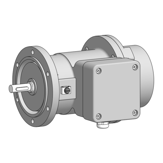
Summary of Contents for Baumer Hübner EExGP 02-TG 74 d
- Page 1 Montage- und Betriebsanleitung Mounting and operating instructions EExGP 0,2 • TG 74 d Tachogenerator mit Ex-Schutzzulassung Tachogenerator with EX approval...
-
Page 2: Table Of Contents
Inhaltsverzeichnis Inhaltsverzeichnis Allgemeine Hinweise ..............................Betrieb in explosionsgefährdeten Bereichen ..................Sicherheitshinweise ..............................Vorbereitung .................................. Lieferumfang ..............................Zur Montage erforderlich (nicht im Lieferumfang enthalten) ........... Erforderliches Werkzeug (nicht im Lieferumfang enthalten) ........... Montage ..................................... Schritt 1 ................................Schritt 2 ................................Schritt 3 ................................ - Page 3 Table of contents Table of contents General notes ................................Operation in potentially explosive environments ................. Security indications ..............................Preparation ..................................Scope of delivery ............................Required for mounting (not included in scope of delivery) ............Required tools (not included in scope of delivery) ................
-
Page 4: Allgemeine Hinweise
Allgemeine Hinweise Allgemeine Hinweise Zeichenerklärung: Gefahr Warnung bei möglichen Gefahren Hinweis zur Beachtung Hinweis zur Gewährleistung eines einwandfreien Betriebes des Gerätes Information Empfehlung für die Gerätehandhabung Der Tachogenerator mit Ex-Schutzzulassung EExGP 0,2 • TG 74 d ist ein generatorisch arbeitendes Präzisions-Drehzahlmessgerät, das mit Sorgfalt nur von technisch qualifiziertem Per sonal gehandhabt werden darf. -
Page 5: General Notes
General notes General notes Symbol guide: Danger Warnings of possible danger General information for attention Informations to ensure correct device operation Information Recommendation for device handling The tachogenerator with EX approval EExGP 0,2 • TG 74 d is a generator-based working precision rotary measurement device which must be handled with care by skilled personnel only. -
Page 6: Betrieb In Explosionsgefährdeten Bereichen
Betrieb in explosionsgefährdeten Bereichen Betrieb in explosionsgefährdeten Bereichen Das Gerät entspricht der Richtlinie 2014/34/EU für explosionsgefährdete Bereiche. Der Einsatz ist gemäß der Gerätekategorie 2 G (Ex-Atmosphäre Gas) zulässig. Gerätekategorie 2 G: - Ex-Kennzeichnung: II 2 G Ex db eb IIC T6 Gb - Normenkonformität: EN 60079-0:2012 + A11:2013 Allgemeine Bestimmungen EN 60079-1:2014... -
Page 7: Operation In Potentially Explosive Environments
Operation in potentially explosive environments Operation in potentially explosive environments The device complies with the directive 2014/34/EU for potentionally explosive atmospheres. It can be used in accordance with equipment category 2 G (explosive gas atmosphere). Equipment category 2 G: - Ex labeling: II 2 G Ex db eb IIC T6 Gb - Conforms to standard: EN 60079-0:2012 + A11:2013... -
Page 8: Sicherheitshinweise
Sicherheitshinweise Sicherheitshinweise Verletzungsgefahr durch rotierende Wellen Haare und Kleidungsstücke können von rotierenden Wellen erfasst werden. • Vor allen Arbeiten alle Betriebsspannungen ausschalten und Maschinen stillsetzen. Zerstörungsgefahr durch mechanische Überlastung Eine starre Befestigung kann zu Überlastung durch Zwangskräfte führen. • Die Beweglichkeit des Gerätes niemals einschränken. Unbedingt die Montagehinweise beachten. -
Page 9: Security Indications
Security indications Security indications Risk of injury due to rotating shafts Hair and clothes may become tangled in rotating shafts. • Before all work switch off all voltage supplies and ensure machinery is stationary. Risk of destruction due to mechanical overload Rigid mounting may give rise to constraining forces. -
Page 10: Vorbereitung
Vorbereitung / Preparation Vorbereitung Preparation Lieferumfang Scope of delivery Gehäuse Housing EURO-Flansch B10 EURO flange B10 Vollwelle mit Passfeder Solid shaft with key Klemmenkastendeckel Terminal box cover Zylinderschraube, M4x30 mm, ISO 4762 Cylinder screw M4x30 mm, ISO 4762 Federring 4, DIN 7980 Spring washer 4, DIN 7980 Kabelverschraubung M16x1,5 mm Cable gland M16x1.5 mm für Kabel ø5...9 mm... -
Page 11: Zur Montage Erforderlich (Nicht Im Lieferumfang Enthalten)
Vorbereitung / Preparation Zur Montage erforderlich Required for mounting (nicht im Lieferumfang enthalten) (not included in scope of delivery) Anbauvorrichtung, kundenspezifisch Installation fitting, customized Befestigungsschraube für Anbauvorrichtung Fixing screw for installation fitting ISO 4017, ISO 4017, M6x16 mm M6x16 mm Federscheibenkupplung K 35, Spring disk coupling K 35, als Zubehör erhältlich, siehe Abschnitt 5.5 available as accessory, see section 5.5 Anschlusskabel Connecting cable... -
Page 12: Montage
Montage / Mounting Montage Mounting Schritt 1 Step 1 Zul. Anzugsmoment: Max. tightening torque: = 100 Ncm 2.5 mm Schritt 2 Step 2 10 mm * Siehe Seite 8 See page 8 Antriebswelle einfetten. Lubricate drive shaft. Die Antriebswelle sollte einen The drive shaft should have as less möglichst kleinen Rundlauffehler runout as possible. -
Page 13: Schritt 3
Montage / Mounting Schritt 3 Step 3 10 mm Schritt 4 Step 4 Zul. Anzugsmoment: Max. tightening torque: = 2...3 Nm 2.5 mm Schritt 5 Step 5 3 mm 17 mm * Siehe Seite 7 oder 8 See page 7 or 8 MB053 - 11055655 Baumer_EEXGP02-TG74D_II_DE-EN (18A1) -
Page 14: Schritt 6
Montage / Mounting Schritt 6 Step 6 3 mm Zul. Anzugsmoment: Max. tightening torque: = 2...3 Nm Ansicht X 17 mm siehe Abschnitt 7.1. View X see section 7.1. ø5...9 mm * Siehe Seite 7 oder 8 See page 7 or 8 Zur Gewährleistung der angegebenen To ensure the specified protection of Schutzart sind nur geeignete Kabel-... -
Page 15: Montagehinweis
Montage / Mounting Montagehinweis Mounting instruction Wir empfehlen, das Gerät so zu It is recommended to mount the device montieren, dass der Kabelanschluss with cable connection facing down- keinem direkten Wassereintritt ward and being not exposed to water. ausgesetzt ist. MB053 - 11055655 Baumer_EEXGP02-TG74D_II_DE-EN (18A1) -
Page 16: Maximal Zulässige Montagefehler Unter Verwendung Der Baumer Hübner Federscheibenkupplung K 35
Montage / Mounting Maximal zulässige Montagefehler Maximum permissible mounting toler- unter Verwendung der Baumer Hübner ance when the Baumer Hübner K 35 Federscheibenkupplung K 35 spring disk coupling is used Geräte mit Vollwelle sollten unter Verwen- Devices with a solid shaft should be dung der Baumer Hübner Federschei- driven through the Baumer Hübner K 35 benkupplung K 35 (Zubehör) angetrieben... -
Page 17: Abmessung
Abmessung - Elektrischer Anschluss / Dimension - Electrical connection Abmessung Dimension 89000 (TG 74 d), 89005 (EEx GP 0,2) 89000 (TG 74 d), 89005 (EEx GP 0,2) Drehrichtung positiv Positive rotating direction ød EEx GP 0,2 12.6 TG 74 d 16.1 Alle Abmessungen in Millimeter (wenn nicht anders angegeben) All dimensions in millimeters (unless otherwise stated) Elektrischer Anschluss Electrical connection Klemmenbelegung... -
Page 18: Betrieb Und Wartung
Betrieb und Wartung / Operation and maintenance Betrieb und Wartung Operation and maintenance Austausch der Kohlebürsten Replace of the carbon brushes Bei Erreichen der minimalen Kohle- When the minimum carbon brush length bürstenlänge (L) von 5,3 mm sollten die (L) of 5.3 mm is reached , the carbon Kohlebürsten ausgewechselt sowie der brushes should be replaced and the com- Kommutatorraum mit trockener Pressluft... -
Page 19: Demontage
Demontage / Dismounting Demontage Dismounting Schritt 1 Step 1 3 mm 17 mm Schritt 2 Step 2 * Siehe Seite 7 oder 8 See page 7 or 8 MB053 - 11055655 Baumer_EEXGP02-TG74D_II_DE-EN (18A1) -
Page 20: Schritt 3
Demontage / Dismounting Schritt 3 Step 3 10 mm 2.5 mm Schritt 4 Step 4 Schritt 5 Step 5 * Siehe Seite 8 2.5 mm See page 8 MB053 - 11055655 Baumer_EEXGP02-TG74D_II_DE-EN (18A1) -
Page 21: Zubehör
Zubehör / Accessories Zubehör Accessories • Federscheibenkupplung • Spring disk coupling K 35 K 35 • Kohlebürsten, • Carbon brushes, siehe Tabelle Abschnitt 8.1. see table section 8.1. * Siehe Abschnitt 3 See section 3 MB053 - 11055655 Baumer_EEXGP02-TG74D_II_DE-EN (18A1) -
Page 22: Technische Daten
Technische Daten Technische Daten 11.1 Technische Daten - elektrisch • Reversiertoleranz: ≤0,1 % • Linearitätstoleranz: ≤0,15 % • Temperaturkoeffizient: ±0,06 %/K (Leerlauf) • Isolationsklasse: • Kalibriertoleranz: ±5 % • Klimatische Prüfung: Feuchte Wärme, konstant (IEC 60068-2-3, Ca) • Leistung: 12 W (Drehzahl ≥3000 U/min) •... -
Page 23: Daten Nach Typ
11.3 Daten nach Typ Min. erforderlicher Lastwider- stand in Abhängigkeit vom Dreh- Max. Anker- Leerlauf- Anker- zahlbereich Betriebs- Wider- spannung (DC) Induktivität [U/min] drehzahl stand 0 - 3000: 0 - 6000: 0 - n (20 °C) [mV/ [kΩ] [kΩ] [kΩ] [U/min] [Ω] [mH]... -
Page 24: Technical Data
Technical data Technical data 11.1 Technical data - electrical ratings • Reversal tolerance: ≤0.1 % • Linearity tolerance: ≤0.15 % • Temperature coefficient: ±0.06 %/K (open-circuit) • Isolation class: • Calibration tolerance: ±5 % • Climatic test: Humid heat, constant (IEC 60068-2-3, Ca) • Performance: 12 W (speed ≥3000 rpm) • Armature-circuit time-constant (τ <150 µs •... -
Page 25: Type Data
11.3 Type data Minimum load required depending on Maximum Open-circuit Armature Armature speed range [rpm] Type operating voltage (DC) resistance inductance speed 0 - 3000: 0 - 6000: 0 - n (20 °C) [mV/rpm] [kΩ] [kΩ] [kΩ] [rpm] [Ω] [mH] EExGP0,2 L-14 ≥0.3 ≥1.2... -
Page 26: Eu-Konformitätserklärung
EU-Konformitätserklärung / EU Declaration of Conformity EU-Konformitätserklärung EU Declaration of Conformity EU-Konformitätserklärung EU Declaration of Conformity Déclaration UE de Conformité Wir erklären in alleiniger Verantwortung, dass die Produkte, auf die sich diese Erklärung bezieht, die grund- legenden Anforderungen der angegebenen Richtlinie(n) erfüllen und basierend auf den aufgeführten Norm(en) bewertet wurden. - Page 27 MB053 - 11055655 Baumer_EEXGP02-TG74D_II_DE-EN (18A1)
- Page 28 Baumer Hübner GmbH P.O. Box 12 69 43 · 10609 Berlin, Germany Phone: +49 (0)30/69003-0 · Fax: +49 (0)30/69003-104 info@baumerhuebner.com · www.baumer.com/motion Version: 89000 (TG 74 d), 89005 (EEx GP 0,2) MB053 - 11055655 Baumer_EEXGP02-TG74D_II_DE-EN (18A1-18.07.2018)
Need help?
Do you have a question about the EExGP 02-TG 74 d and is the answer not in the manual?
Questions and answers