Table of Contents
Advertisement
Quick Links
Advertisement
Table of Contents

Related Manuals for AMC A Series


Summary of Contents for AMC A Series
- Page 1 User A SERIES Manual Amplifier...
- Page 2 The product should be located away from heat sources such as radiators, heat vents, or other devices that produce heat. The product should be connected to a power supply that is described in the operating instructions or are marked on the product. USER MANUAL A SERIES Amplifier...
- Page 3 Table of contents Before you start Introduction ..............................2 Features ................................2 Operation Front panel ................................3 Rear panel................................3 Front and back panel functions ......................4 Specifications General specifications ...........................5-6 USER MANUAL A SERIES Amplifier...
- Page 4 These stereo power amplifiers have complete protection functions and superior performance. FEATURES • DC and thermal overload protection • -115VAC 60Hz, -230VAC 50Hz select switch and IEC. • Short circuit and speaker protection • Balanced phoenix connectors, screw terminal speaker connectors • Power ON, Clip, Signal, and Protect LED indicators for each channel. • Stereo/bridge mode. • Roadworthy, rugged double rack space (1U) housing • 2 variable speed fans for cooling USER MANUAL A SERIES Amplifier...
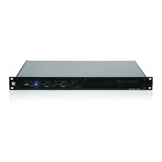
- Page 5 Operation Front Panel 1. Power switch | 2. Power LED indicator | 3. Protection LED indicator | 4. Channel signal LED indicator 5. Channel clipping LED indicator | 6. Channel level control Rear Panel 1. Fans 2. Input connectors 3. Mode selector switch 4. Output connectors 5. AC voltage selector switch 6. Fuse holder 7. AC power connector USER MANUAL A SERIES Amplifier...
- Page 6 The fan speed is varied automatically to maintain the proper internal operating load impedance is too low. When this LED lit up, turn OFF the device and check temperature. output connections. SIGNAL LED INDICATOR This LED illuminate when input signal greater than 100 mV is present. CLIP LED INDICATOR This LED illuminate when amplifier output is within 3dB of clipping. Occasional blinking is acceptable, but if LED lights on more than intermittently. turn down either the power amplifier level or reduce the output level of the preceding component to avoid audible distortion. USER MANUAL A SERIES Amplifier...
- Page 7 General Specifications A Series amplifier A100 A200 4Ω / EIA 1 kHz / 0.1% THD (Stereo mode) 100W 200W 8Ω / EIA 1 kHz / 0.1% THD (Stereo mode) 130W 8Ω / EIA 1 kHz / 0.1% THD (Bridge mode) 200W 400W Input Sensitivity 0.775 Vrms (0 dBu) Input Impedance 10kΩ unbalanced 25 Hz - 25 kHz: ±1 dB Frequency Response 5 Hz - 50 kHz: ±3 dB Distortion (SMPTE-IM) < 0.03% Signal to Noise Ratio (20 Hz - 20 kHz) 8Ω > -100 dB Damping Factor (1 kHz and below) > 400 at 8Ω USER MANUAL A SERIES Amplifier...
- Page 8 General Specifications A Series amplifier A100 A200 Full short circuit, open circuit, thermal. Amplifier Protection Stable into reactive or mismatched loads Load Protection Turn-on/off muting, current limiter Controls Front: AC switch, channel 1 & 2 volume knobs Power-on: Blue LED / Signal: Green LED (1 per channel) / Clip: Red Indicators LED (1 per channel) Protect: Red LED Connectors (each channel) Input: balanced Phoenix Output: Screw terminals...
Need help?
Do you have a question about the A Series and is the answer not in the manual?
Questions and answers