Table of Contents
Advertisement
Quick Links
Advertisement
Table of Contents

Related Manuals for nanoradar CAR28T


Summary of Contents for nanoradar CAR28T
- Page 1 CAR28T Millimeter Wave Radar User manual...
- Page 2 Any improper use may cause damage or injury, and Nanoradar would not bear the corresponding loss and liability. Product copyright is retained by Nanoradar. Reproduction in any form shall not be done without permission. The use of this product and manual shall not be pursued liability for the patent.
-
Page 3: Table Of Contents
2 Matters needing attention in use................4 3 Shipping list......................5 3 Quick-to-use steps....................5 4.1 Cables installation.................... 5 4.2 The installation and coordinate system of CAR28T........5 4.3 Test and use...................... 7 4.4 Online upgrade for product firmware..............9 5. Data parsing for CAN interface................10 5.1 CAR28T configuration (Sensor Configuration)..........11... -
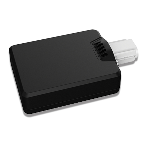
Page 4: Brief Introduction Of Car28T
CAR28T compacts 96 × 57 × 20mm, detection range is 50 meters. With its leading performance, cost-effective feature, integrated peripheral interface (CAN interface), BSD, FCTA, RCTA, EAF and other functions, car28T can meet the rapid growth of the automotive industry safety support driving demand. -
Page 5: Shipping List
In the blind spot detection and related applications, there should be an installation height of 500 ~ 1200mm to the ground for CAR28T, and a 25 ° angle between the radar antenna surface and the car body. The installation diagram is as follows:... - Page 6 Fig4. Module backward installation diagram The installation parameters are as follows: Table 2 Module installation parameters Note: In forward applications, the coverage width of the blind area on both sides is higher. It will be recommended to adjust the installation azimuth to 45°. However, in backward applications, it has a higher requirement for the longitudinal coverage in the BSD / LCA and others.
-
Page 7: Test And Use
As shown in the left figure, the dotted line indicates the origin of the target angle, and the distance from the dotted line to the left border is 26 mm. The target angle of CAR28T test is the azimuth distance from the radial distance (linear distance). The speed is positive when the target is near the radar sensor, and the speed is negative when the target is far from the sensor. - Page 8 Fig8. CANBUS connection and test diagram Note: When the connection is correct and CAR28T is started for the first time, CAR28T will give a 1-second "beep" tone. When CAR28T is connected to the 12VDC power supply, the green light (POWER) in the USBCAN will continue to light, and yellow light will continue to flash when the CAR28T is operating normally.
-
Page 9: Online Upgrade For Product Firmware
The suggested test sites: CAR28T should be tested in open areas outdoors, due to that there are many interference for the indoor test, which will lead to the discontinuous target track. 4.4 Online upgrade for product firmware CAR28T support online upgrade. -
Page 10: Data Parsing For Can Interface
Fig10. CAR28T radar upgrade tool interface 5. Data parsing for CAN interface CAR28T radar supports CAN interface. The communication network of CAN Bus complies with ISO11898-2 standard, with the transmission rate of 500bit/s. CAR28T transmits radar signals to the surroundings and processes the received signals in multiple steps, to collect the targets groups and target tracks. -
Page 11: Car28T Configuration (Sensor Configuration)
0x60A, 0x28TB and 0x28TC. If the radar ID is configured as 1, then its Message ID is 0x210, 0x410, 0x61A, 0x71B, 0x71C, and so on. 5.1 CAR28T configuration (Sensor Configuration) CAR28T radar is configured through 0x200 messages. And the structure of radar configuration message is as the following table: Table 5 the structure of radar configuration message The description for each field in the structure of radar configuration message is as the followings. - Page 12 For reading or writing parameters, CAR28T will reply a message that contains the results of writing parameters or the returning of the parameters to read. RadarFeedback defines the format of the replied message. When configuring CAR28T, the definition of Parameter is different for different DataType.
- Page 13 When the obtained radar version is read-only, in getting the radar version, do not fill any value in the Master Version, Second Version, Step Version, and CAR28T ignore these values. When CAR28T receives a message of obtained radar version, the current radar version information will fill up the fields in the reply message of 0x400.
- Page 14 The installation direction of CAR28T affects the angle calibration in the algorithm. After installing the CAR28T, the installation direction field of the radar needs to be configured, and the program will be calibrated according to the installation direction. The radar installation...
-
Page 15: Radar Back (Sensor Feedback)
5.2 Radar back (Sensor Feedback) Each time the host computer or other MCU sends the configuration signal to CAR28T, CAR28T will immediately return the execution result. The reply format of the reply is shown in the following table. In the radar reply, only Bit7 is different. Bit7 in RadarConfiguration is defined as R / W, and RadarFeedback is defined as the result of the configured execution. -
Page 16: Radar Status (Radar Status)
5.3 Radar status (Radar Status) The message 0x60A includes radar status message. And the structure of radar configuration message is as follows. Table 16 the structure of radar status message(0x60A) The description for each filed in radar status message is as follows. Table 17 the description for radar status message(0x60A)... - Page 17 The target output status data message format for CAR28T system is as shown in the table, which NoOfCluster represents the number of detected targets, and the value of RollCount value lies between successive cycles of 0-1-2-3-0-1-2-3 ••••••. When the host computer or an external MCU cannot process the output data of CAR28T sensor in time, it will cause the received RollCount value to be discontinuous.
-
Page 18: Target Output Information (Target Info)
5.5 Target output information (Target Info) The message format for Car28T target output is as follows. Table 20 the structure of target information (0x28TC) Message 0x28TC contains the target's distance, angle, speed and other information. When the radar sensor is working and the target is detected, the target output state message appears after the CAR 28T system status message, and finally there will be the target output information message. -
Page 19: Data Parsing Examples
- Range = (RangeHValue*256 + RangeLValue)*0.01 - Azimuth = AzimuthValue*2 – 90 - RollCount = RollCountValue - Verl = (VrelHValue*256 + VrelLValue) *0.05-35 - SNR = Value-127 The reflection Radar-Cross Section (RCS), the target range (Range), the target velocity (Verl), the target azimuth (Azimuth), and the Signal Noise Ratio (SNR) can be obtained by these calculations, therefore to accurately detect the target. -
Page 20: Installation And Notes For Risks
3. Keep away from the motor actuator and drive. Installation position: The CAR28T radar sensor is recommended for installation in the position of the vehicle bumper. Same as the radome, the bumper material will also have a greater impact on radar performance. -
Page 21: Notes For Risks In Use
◆The equipment needs to be inspected daily before it is put into service. 8 Frequently asked questions (FAQ) (1) Q: When CAR28T millimeter wave radar is installed in the car, the output of the ID is the same? A: Each radar has its own ID. And also radar ID is related to its installation position.ID can be read out from the CAN message. -
Page 22: References
9 References [1] White paper on CAR28T millimeter wave radar [2] User manual for the general management system of Nanoradar mmw radar [3] User manual for Nanoradar's radar upgrading tool WP015(v1.0)2017-05-05...
Need help?
Do you have a question about the CAR28T and is the answer not in the manual?
Questions and answers