
Related Manuals for JUMO 202711/10


Summary of Contents for JUMO 202711/10
- Page 1 JUMO Simulator for pH/redox type 202711/10 Operating Manual 20271110T90Z001K000 V2.00/EN/00727307/2019-10-18...
-
Page 3: Table Of Contents
Contents Contents Introduction ..........4 Safety information . -
Page 4: Introduction
Introduction 1 Introduction Safety information 1.1.1 General Information This manual contains information that must be observed in the interest of your own safety and to avoid material damage. This information is supported by symbols which are used in this manual as indicated. Please read this manual before starting up the device. -
Page 5: Description
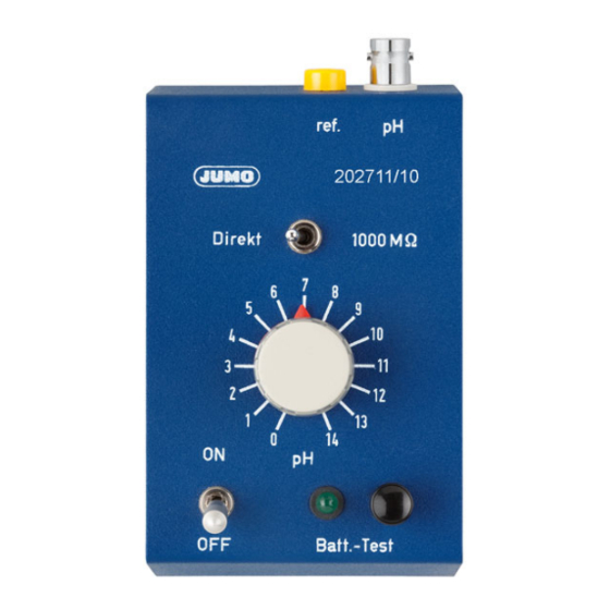
1 Introduction Description 1.2.1 Intended use The simulator for pH/redox is used for startup, for calibration, and for inspecting/troubleshooting pH and redox transmitters. 1.2.2 Operating principle The simulator is used to check that technical pH and redox measurement instruments are working cor- rectly. -
Page 6: Identifying The Device Version
00082906 for testing measuring devices with a BNC socket as the pH input Connecting cable for pH simulator 202711/10, BNC to N-connector, length 1.1 m, for 00082906 testing the pH meter run from the electrode head (for standard electrodes with an N-/ S7-/S8-plug head), not suitable for electrodes with integrated temperature probes Connecting cable for pH simulator 202711/10, BNC to Shield-Kon®(free cable end with... -
Page 7: Electrical Connection
Electrical connection 3 Electrical connection Connecting cables You can find suitable connecting cables for the device in chapter 2.3 "Accessories", Page 6. -
Page 8: Operation
Operation 4 Operation General information You switch the pH simulator on or off using the "ON/ OFF" switch. To switch it on, pull out the switch- ing knob first (1) and then flick it upwards (2). To switch it off, pull out the switching knob again and flick it downwards. -
Page 9: Testing The Input Of A Ph Transmitter
4 Operation Testing the input of a pH transmitter 4.2.1 Transmitter settings Depending on the device configuration (manual temperature specification or automatic temperature compensation), you first have to set the reference conditions for the temperature compensation on the transmitter. In the case of a manual temperature specification, you have to set the temperature to 25 °C. In the case of automatic temperature compensation, the temperature of the connected temperature probe must be adjusted to 25 °C. -
Page 10: Calibrating Ph Transmitters And Checking Connected Components
4 Operation Calibrating pH transmitters and checking connected components 4.3.1 Transmitter settings Depending on the device configuration (manual temperature specification or automatic temperature compensation), you first have to set the reference conditions for the temperature compensation on the transmitter. In the case of a manual temperature specification, you have to set the temperature to 25 °C. In the case of automatic temperature compensation, the temperature of the connected temperature probe must be adjusted to 25 °C. -
Page 11: Allocating The Current/Ph Value
4 Operation 4.3.3 Allocating the current/pH value The following diagram shows how the correct current values on the transmitter's actual value output are allocated to the pH values set on the pH simulator, for the measuring range 2 to 12 pH ≙ 0 to 20 mA. -
Page 12: Testing The Input Of A Redox Transmitter
4 Operation Testing the input of a redox transmitter 4.4.1 Transmitter settings The display of the transmitter must be set to "mV". In the case of customer-specific settings, the operator/ user has to perform the calculation themselves. 4.4.2 Settings and steps for operating the simulator 1. -
Page 13: Calibrating Redox Transmitters And Checking Connected Components
4 Operation Calibrating redox transmitters and checking connected components In principle, the process used for checking a redox transmitter is similar to the process used for checking a pH transmitter – as described on page 10. Depending on the measuring span of the redox transmitter to be calibrated, set values between 7 pH and 0 pH on the simulator's pH selection switch. -
Page 14: Allocating The Current Value/Redox Potential
4 Operation 4.5.1 Allocating the current value/redox potential The following table shows how the correct current values on the transmitter's actual value output are al- located to the simulated redox potential on the simulator using the set pH values for the measuring range 0 to 500 mV ≙... -
Page 15: Maintenance
Maintenance 5 Maintenance Replacing used batteries To replace a used battery, proceed as follows: 1. Remove the 4 screws from the back cover of the device. 2. Pull the two housing parts apart. 3. Replace the used batteries. 4. Put the two housing parts back together again. 5. -
Page 16: Technical Data
Technical data 6 Technical data Simulation range 0 to 14 pH in increments of 1 pH or redox potential +414 mV to -414 mV in in- crements of 59 mV Accuracy ±1 % of the set pH value Reference temperature 25 °C Output resistance Depending on the switch position: 1 kΩ... -
Page 17: China Rohs
China RoHS 7 China RoHS... - Page 18 7 China RoHS...
- Page 20 JUMO GmbH & Co. KG JUMO Instrument Co. Ltd. JUMO Process Control, Inc. Street address: JUMO House 6733 Myers Road Moritz-Juchheim-Straße 1 Temple Bank, Riverway East Syracuse, NY 13057, USA 36039 Fulda, Germany Harlow, Essex, CM20 2DY, UK Delivery address:...
Need help?
Do you have a question about the 202711/10 and is the answer not in the manual?
Questions and answers